www.gt4dc.co.uk
http://www.gt4dc.co.uk/forum/

"La GrOsse" cooling mod
http://www.gt4dc.co.uk/forum/viewtopic.php?f=1&t=4350
Page 1 of 3

Author:  bozo-merlin [ Mon Dec 20, 2010 2:21 pm ]
Post subject:  "La GrOsse" cooling mod

I want to share what MetalMachines® did for me according to the specification guidance.

Inspired by the 3S-GTE cooling post,TTE style, Sunny hard pipe, Alanv (OC.net) Corolla rad, ...


Basically a ST185 with gen.3 engine.

Previous set up : Golpher rad, 1.3 cap, TRD stat, air duct, alloy tap everywhere to avoid air leak, twin SPAL 11" pusher, 40% Ethyl / 60% water, washer bottle as unpresurised expansion tank, 13rows GB cooler, 13 rows engine cooler, 12mm spacer for end of bonnet.

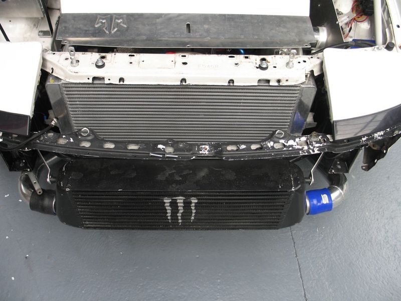
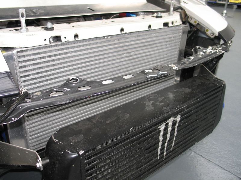
Radiator and EVO8 IC arrangement
Image

Front face without bumper
Image

Alloy taping in air duct
Image

Alloy taping engine side
Image

Silicon hose (can see airbox and piping path)
Image

Front bumper on, under signal light for oil cooler, we can see the cold air pick up too.
Image

Alloy air duct pushing the bumper grid
Image


New set up : Sierra RS500 rad, swirlpot, header tank, alloy hard pipe, polyamide degazing tube, 1.3 cap, TRD stat, 30% Ethyl / 65% water / 5% water wetter, 13rows GB cooler, 16 rows engine cooler (not complete yet), 12mm spacer for end of bonnet, air duct (not complete yet), alloy tap everywhere to avoid air leak (not complete yet), twin fan puller (ebay fan are craps, SPAL puller very expensive, have to decide ...) .

Rad on car between rail
Image

Image

More clearance between rad and turbo (hope it will keep away some of the heat soak)
Image Image

Custom swirlpot under construction
Image

Swirlpot installed
Image

Swirlpot clearance (able to install a 4" strait intake for a nice GT30 antisurged)
Image Image

Expansion tank after welding
Image

Modified engine silentbloc to clear expansion tank
Image

Expansion tank installed
Image

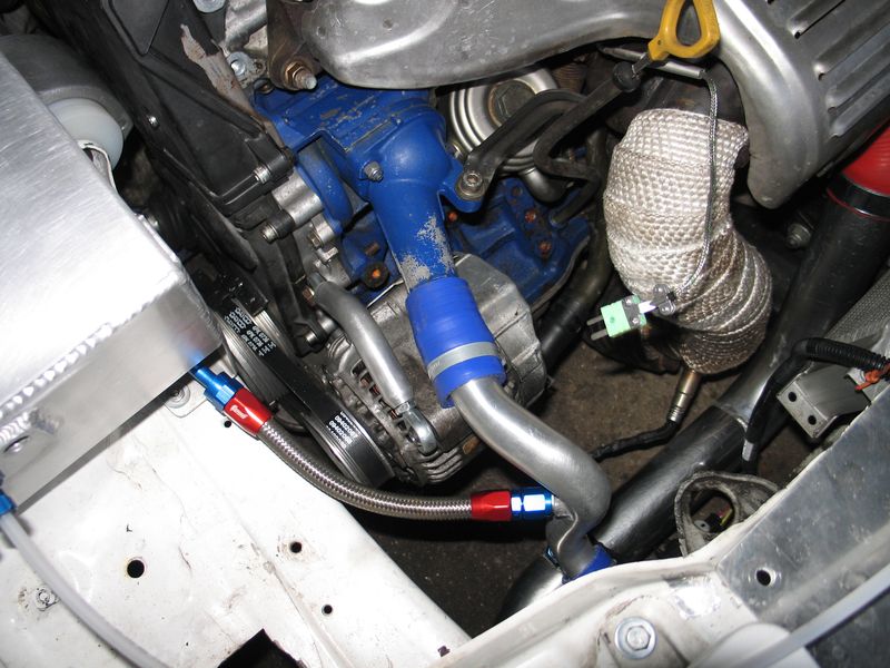
Cold hard hose (and relocated alternator test fitting)
Image

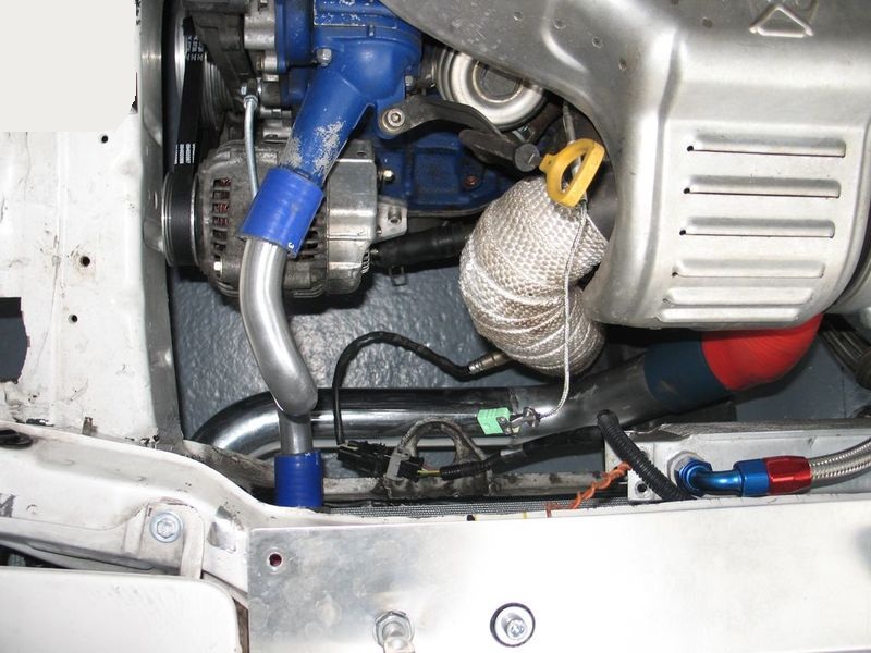
Cold hard hose complete and connected
Image


I don't find a good position for the EVO8 IC as i don't want it to seat to low, i decide to source something else and go for a second hand aftermarket subaru one which fit nice behind the bumper grid
Image
2nd hands Subaru part which explain the "Monster" on IC :lol:

New hot side piping for new IC
Image
90° bend are avoid !

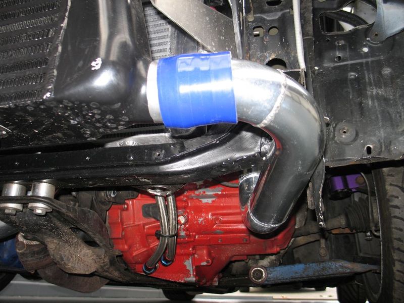
Hot side piping installed
Image

New cold side piping too
Image
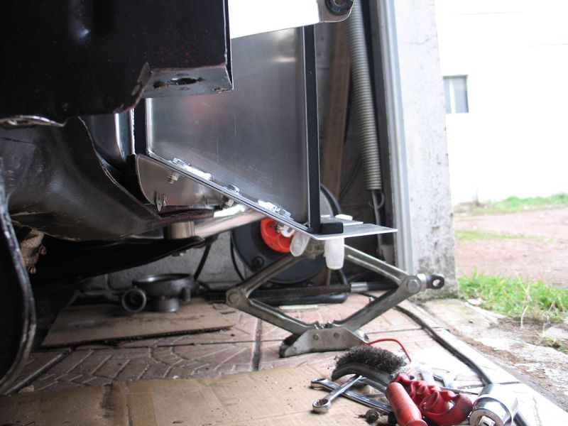
I said i have a low track car, from lowest point of exhaust to floor there is 34mm, have tried to correct bump steer, sort something better than OEM but not perfect yet

Try to do it as short as possible
Image

Relocate the IAT sensor too for accurate reading (and it works great)
Image


Complete with polyamide degazing tub installed
Image

Image

Coolant system capacity is increased to 11.7L + 1.2L air (for expansion)

4th blank plug on the expansion tank if one day i want to run a post turbo alloy cooling tube (like the PAS one) and an electrical water pump.

On those last two pics you can see the beginning of the new air duct, with MetalMachines® logo pressed on, need times now to complete it and share more pics with you.

Author:  Diceman [ Mon Dec 20, 2010 2:29 pm ]
Post subject: 

very nice indeed :-)

Author:  Kris [ Mon Dec 20, 2010 2:43 pm ]
Post subject: 

Great work!

Author:  RoAdbOy [ Mon Dec 20, 2010 2:49 pm ]
Post subject: 

wow! awesome work :)

Author:  Sunny [ Mon Dec 20, 2010 3:41 pm ]
Post subject: 

Hi,

5 of 5 stars 8)

greetz

Author:  Nibbles [ Mon Dec 20, 2010 5:03 pm ]
Post subject: 

I think the monster logo would be better suited to the RS500 rad. :lol:

Looks like an excellent setup, given me some ideas as I need to do something with my 185 cooling.

Author:  Diceman [ Mon Dec 20, 2010 5:08 pm ]
Post subject: 

Oooh - info also required on yoru alternator re-location :-)

Author:  ST185pinjo [ Mon Dec 20, 2010 8:51 pm ]
Post subject: 

Very nice! 8)

Author:  Sunny [ Mon Dec 20, 2010 9:30 pm ]
Post subject: 

Hi,

does i ask you for the wall thickness of the water pipes?

greetz

Author:  bozo-merlin [ Mon Dec 20, 2010 10:21 pm ]
Post subject: 

Thanks all for the comment, i do it like this because of your knoledge sharing here and because this time i want to do it right with no more over heating issue.

I think there is 2 thing that can uprated this setup : an electric water pump and a triple flow design rad (which can be done on the "Monster" RS500 rad) but to be fair i think 105°+C is an old story now.


Sunny,
30 OD, 27 ID means 1.5mm

Oulet water ID is 27mm, we choose this pipe because of this

Don't control Inlet water ID but i think it is similar to Oulet

They are 1 piece part, heated and then hand bended

We machined an ally log for silicone 32mm link, 25mm long, 33 OD, 30.2 ID, and weld at each end.

Every thing have been leak tested under 4 bar and is leak free, i know i could use a formula 1 rad cap, pipe won't leak or go mad.

Author:  Muddy Water [ Tue Dec 21, 2010 10:16 am ]
Post subject: 

WOW...very impressed.
A lot of thought gone on here, thanks for sharing.

Author:  Sunny [ Tue Dec 21, 2010 4:34 pm ]
Post subject: 

Hi,

many thanks

greetz

Author:  bozo-merlin [ Fri Feb 18, 2011 10:17 am ]
Post subject: 

Small Update

As i have change both rad and IC i need a new design AirDuct (it performed so well on the previous set up)

What it looked before any brainstorming with myself (:lol:)
Image

Image


This time IC is just behind the front bumper, the Airduct can't go from the rad to the bumper, but i have enought space between rad and IC.

After some cardboard template, i tTook some 1.5mm aluminium sheet and some foam sealant


Ended to this
Image

Image

Image


We can see here that the foam sealant will take care of vibration and air leak, bottom is not completly pressed, top is not at all.
Image


Now it is time to put back the IC, gap between rad and IC is 134mm, the aluminium sheet is 131 and foam sealant is 10mm thick each side.
You easily understand that fiiting the IC is a pita as i need to compress a lot the foam
Image

Image

Image

Image


A front view to see where air can pass to see the rad
Image


My car is a 110% track car and my front CS bumper have suffer from gravel tap once or twice :roll: so is not in its best status, i decided to mod to "try to control" airflow
Cut the middle number plate holder, put 2 aluminium sheet each side of the IC (funnel shape) and some alloy tap
Image
Poor Iphone quality


Some mat black paint on the sheet and of course some guard to protect everything (25mm gap from guard to IC)
Image
Poor Iphone quality

Image
Poor Iphone quality


I now need to complete the oil rad set up to share the end of the front ducting.

Author:  Gary ST165 [ Fri Feb 18, 2011 11:51 am ]
Post subject: 

excellent :)

Author:  Diceman [ Fri Feb 18, 2011 1:25 pm ]
Post subject: 

damn good work :-)

Page 1 of 3 All times are UTC + 1 hour
Powered by phpBB® Forum Software © phpBB Group
http://www.phpbb.com/