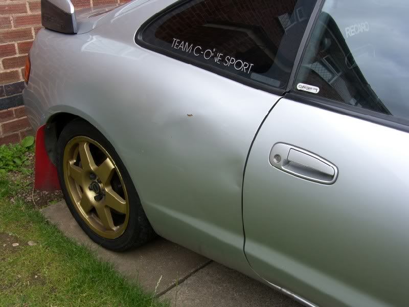
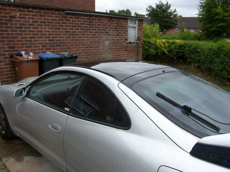
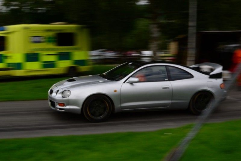
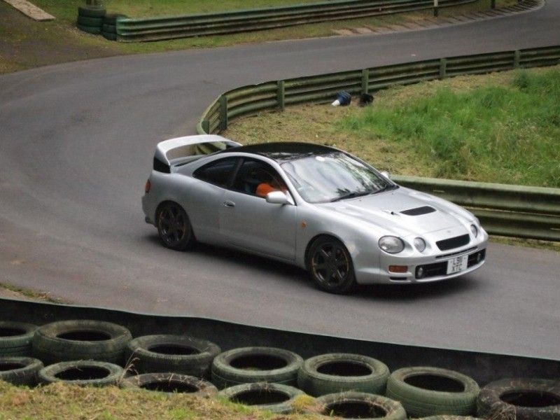
Well since the last update, I have finally driven the car! It was a voyage of discovery, as I have not driven the car since the day I bought it, so the first drive was to find out if anything else was wrong that I had not identified.
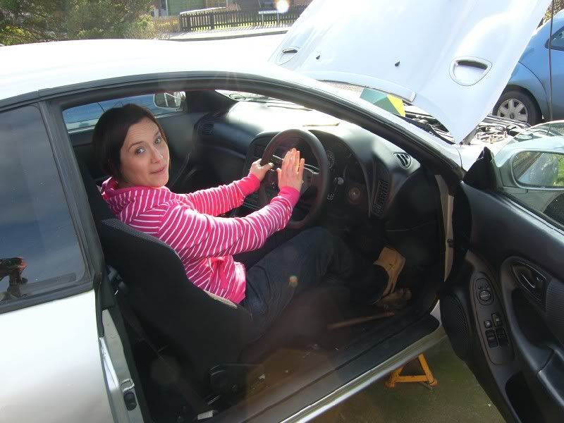
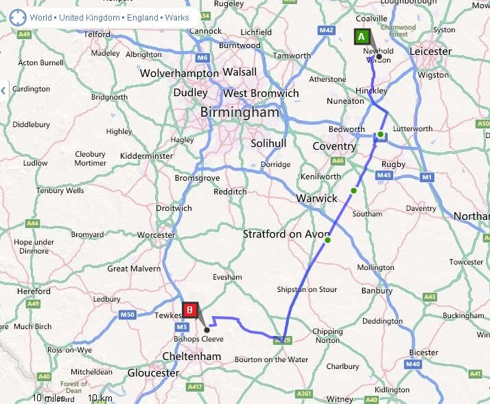
Whilst I was away on my last trip, Michelle my wife picked up the car from the garage for me, a trip that involved 2 buses, 2 trains and a taxi! Wonderful wife

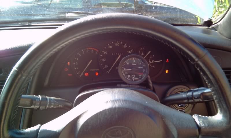
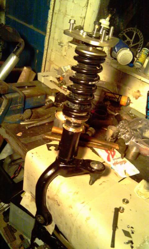
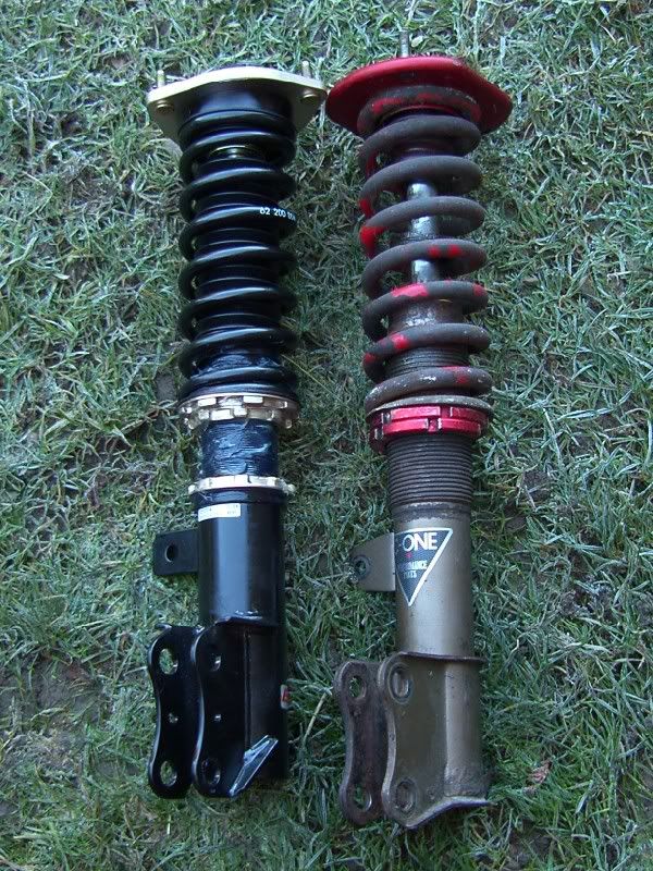
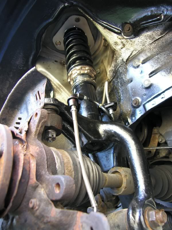
When I got back I could finally drive it, and the result was overall very good. The suspension was brilliant, well damped with good control, stiff enough to not roll but compliant enough to not be jarring. I would compare the ride to my E39 535i sport, just a little stiffer.
The brakes are amazing, I warmed the tyres up, checked for traffic and decided to bed the pads in. The first stop was very good, the second made me feel nauseous! The braking power is incredible!
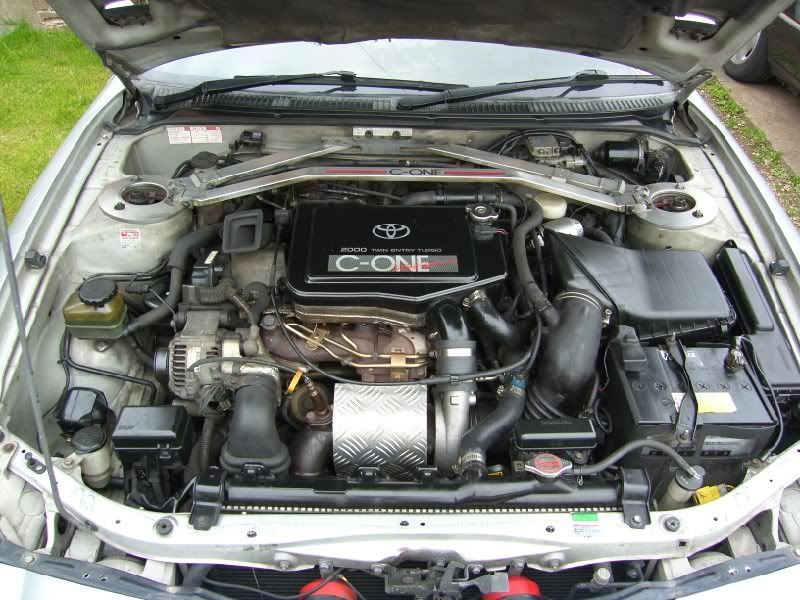
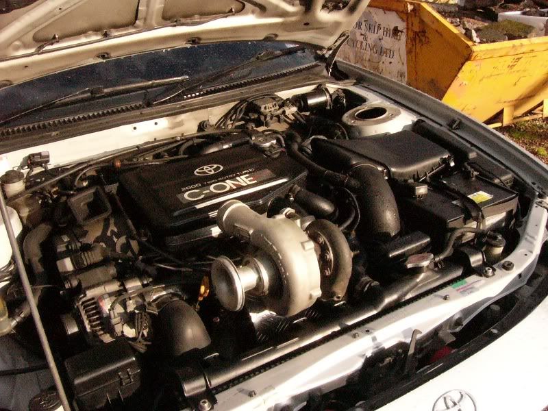
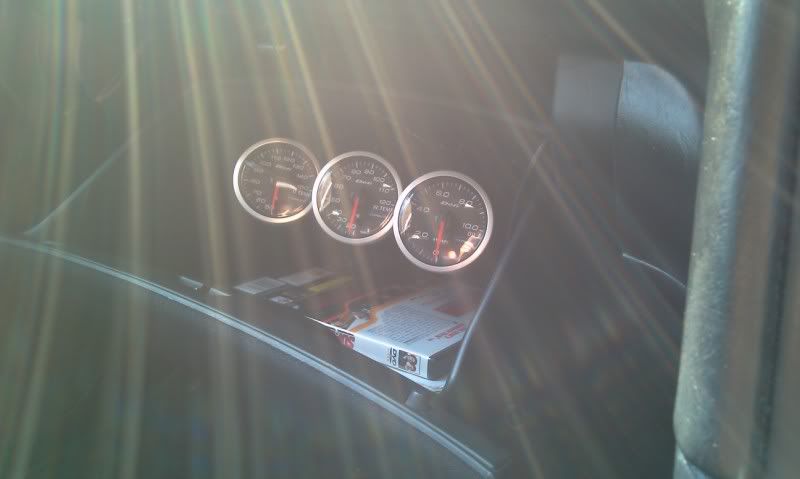
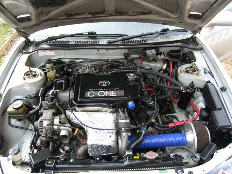
The engine is strong and has no real issues except for needing more boost
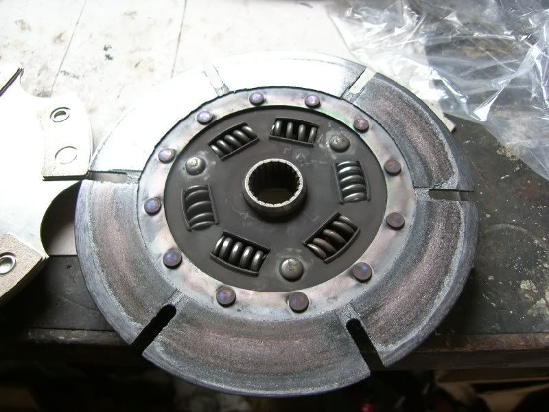
The drive train does have some issues, I am unsure how much of it comes from the fact the diff is very tight and how much come from wear, the symptoms are whining / grinding on overrun and heavy vibration on low RPM wide open throttle acceleration.
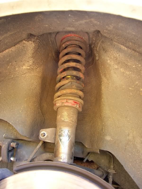
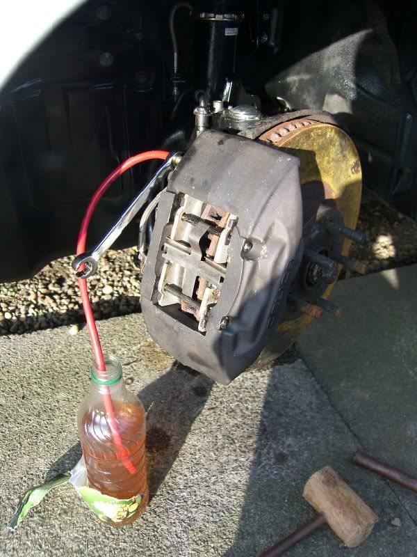
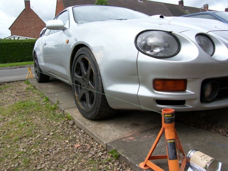
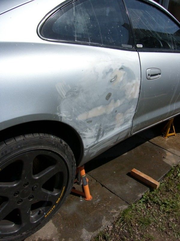
I took the decision to remove the diff and inspect the bearings and gear setup.
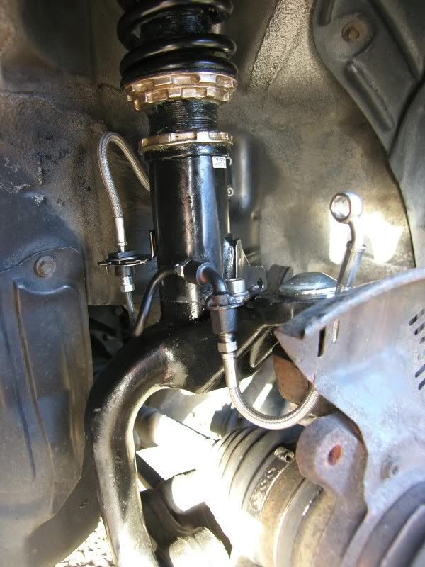
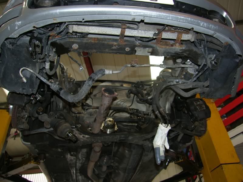
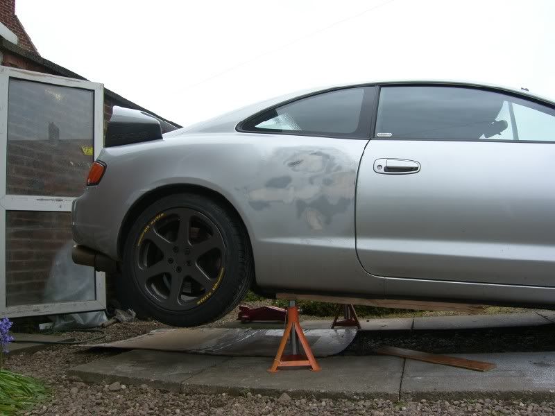
Car in the air –
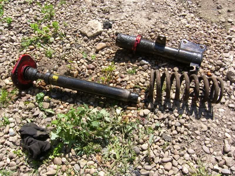
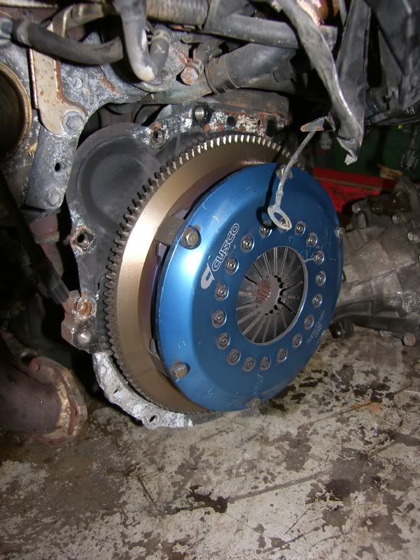
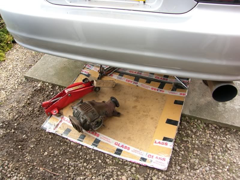
Diff out –
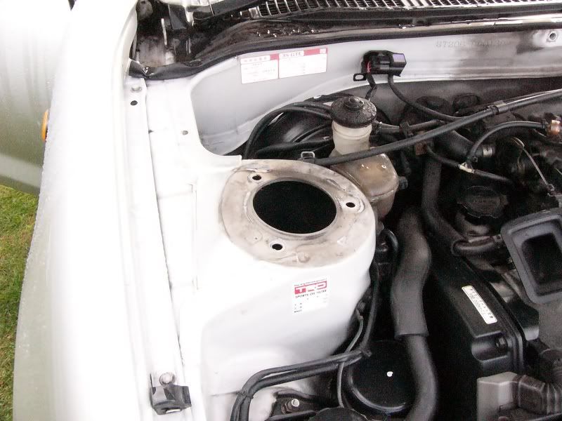
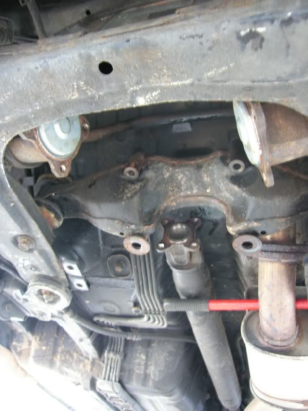
Hole left! –
This is an excerpt from my investigation -
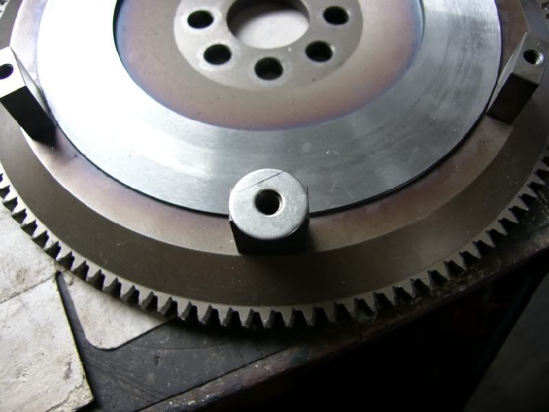
I have done some more investigation, the diff is out and I have cleaned the crown wheel and pinion. This is what I have learnt so far -

Ring Gear Tooth Nomenclature
A – Top. The top of the gear tooth, a.k.a. Face, Top Land
B – Root. The bottom of the gear tooth, a.k.a. Flank
C – Heel. The outside-diameter-end of the gear tooth
D – Toe. The inside-diameter-end of the gear tooth
E – Coast. The concave side of the gear tooth*
F – Drive. The convex side of the gear tooth*
* Don’t be mislead by the terms “coast” and “drive”, as the ring-gear can be driven by the pinion on either side of the teeth. Which side of the teeth will depend on if the gear-set is standard or reverse spiral and whether the vehicle is going forward or in reverse.
Thanks pirate4x4!
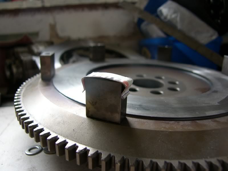
I used a paint pen on the teeth and then ran the gears round under a bit of load.
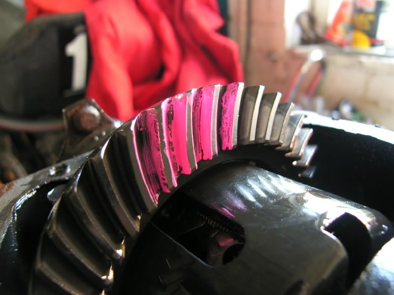
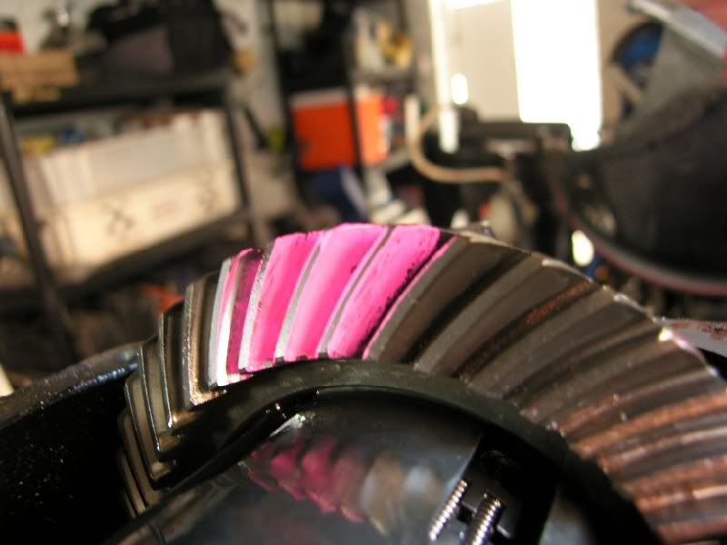
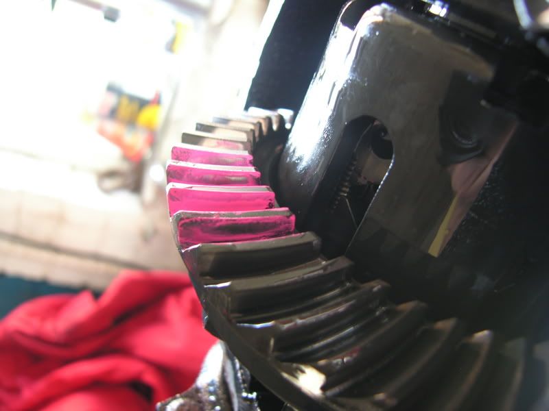
So this is what the contact pattern looks like on mine, sorry about the photos, it is really hard to get a picture of the marks left!
'coast' side -
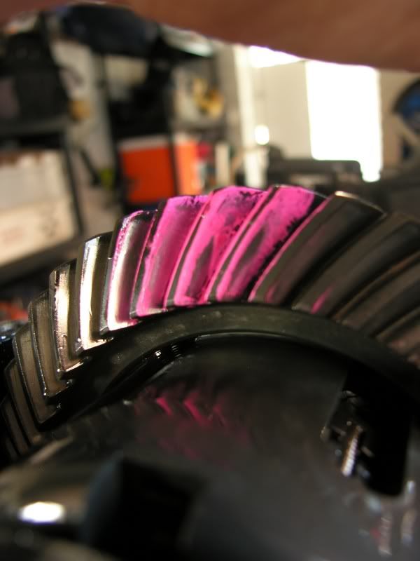
'drive' side -
toyota manual says -
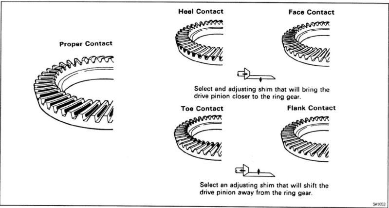
Differentials.com says -

So from what I can see, I am between the bottom two images, maybe slightly too much backlash? I have dial gauge on order so I can measure that, I will update when I get back from Monaco

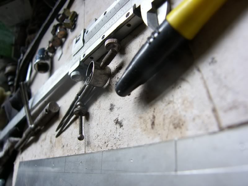
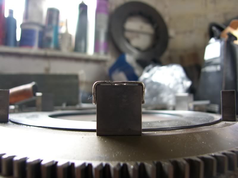
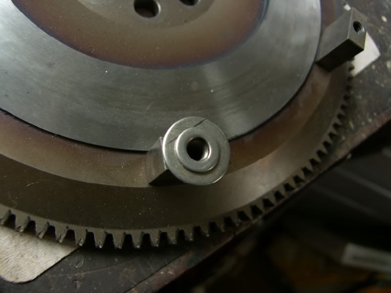
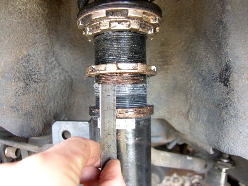
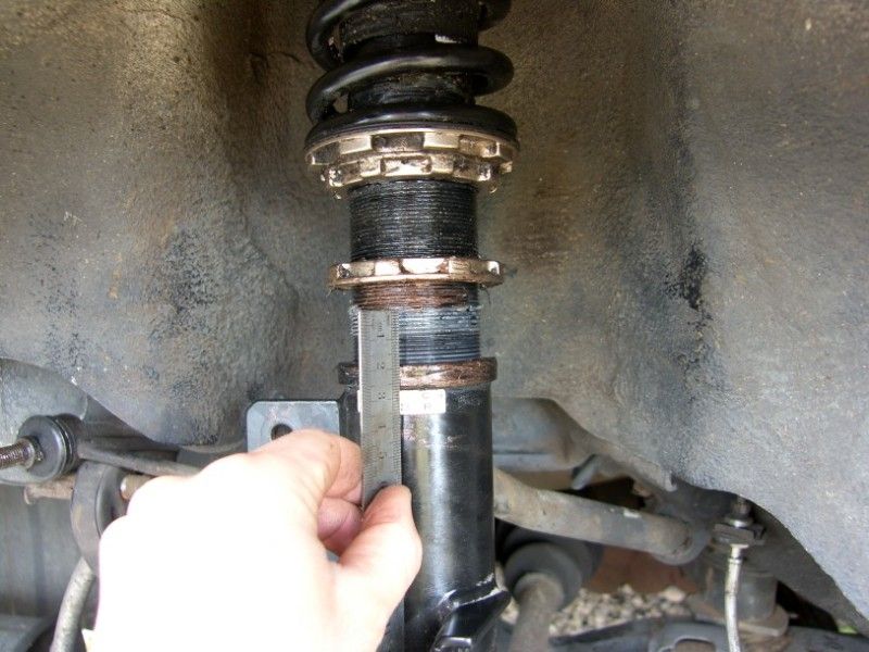
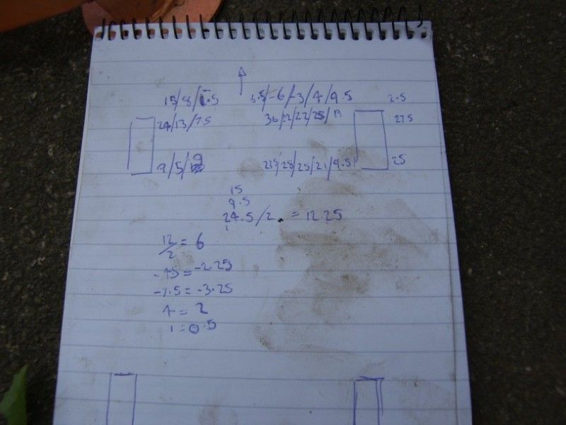
So at this point, I have arrived back from Monaco and I can continue the investigation, I put the dial gauge on the case and measured the crown wheel backlash –
Zeroed out -
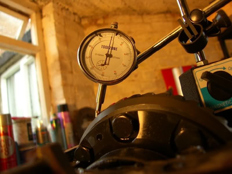
Rocked back and forth –
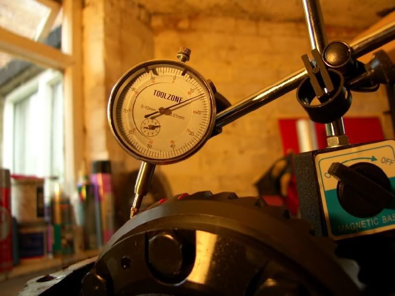
So that makes 130 microns, bang on the Toyota set up figure. So I there is nothing wrong with the diff or set up :S
I think that the noises on overrun are to do with the very tight 2 way LSD, having no experience of it it is kinda hard to tell.
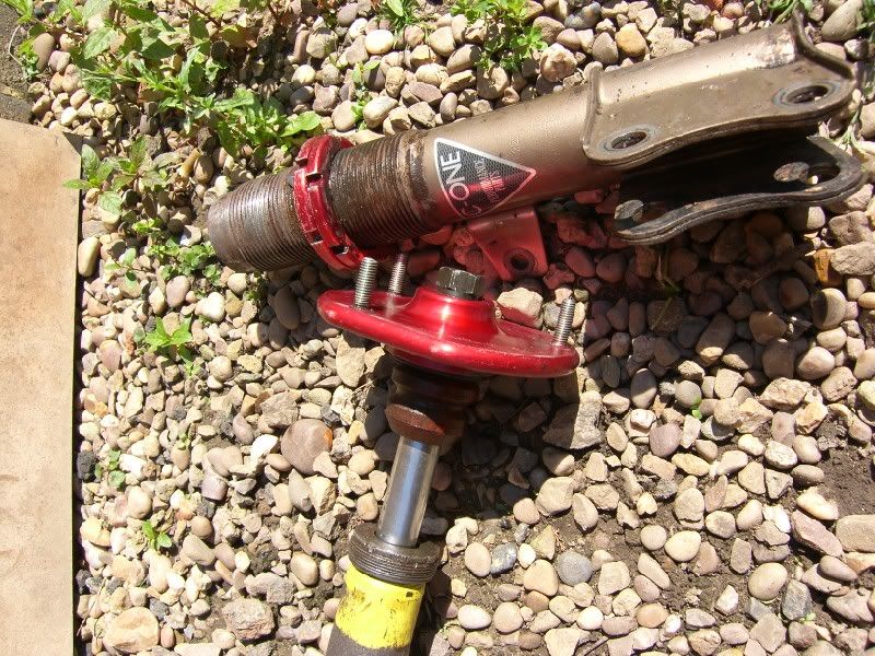
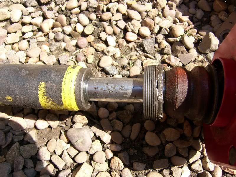
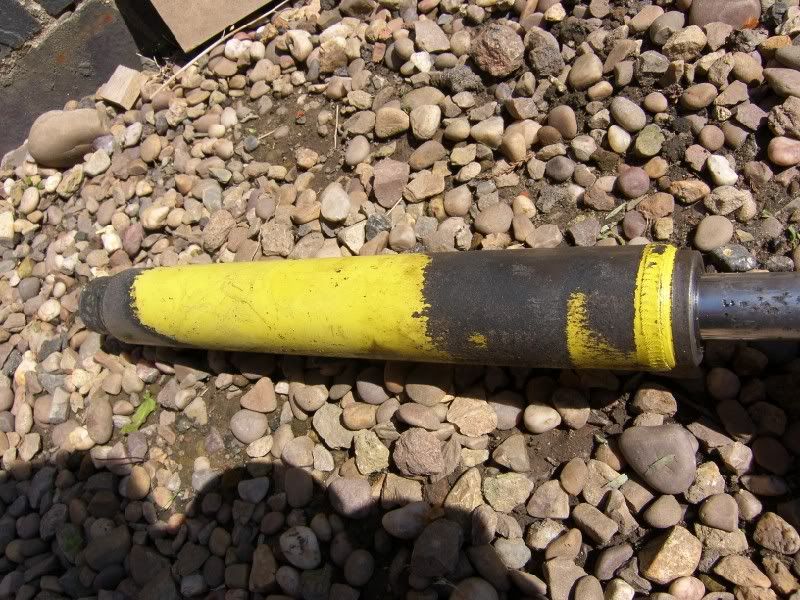
The prop was inspected whilst everything was off, the support bearings were fine, CV feels fine, the UJ’s have tight points so I think they are on their way out and are staked in so no replacing them!
So I built the diff back up and filled it with 1100cc of Motul EP90 Mineral oil, LSD specific

Everything was built back up and put back on the ground.
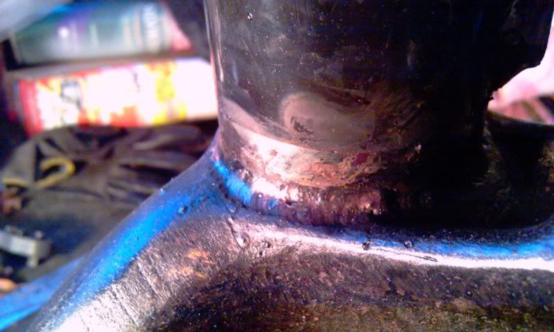
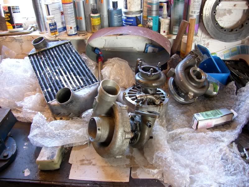
Whilst at the front of the car I noticed a small exhaust leak around the turbo, and then noticed joy of joys a crack on the down pipe!
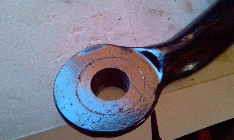
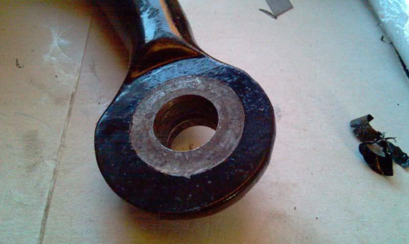
So I pulled the down pipe off an then found this –
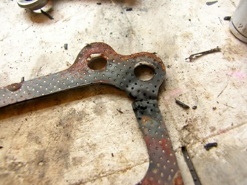
One cooked gasket!
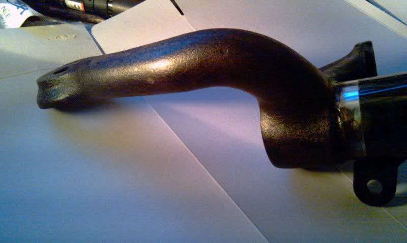
This is the crack on the down pipe –
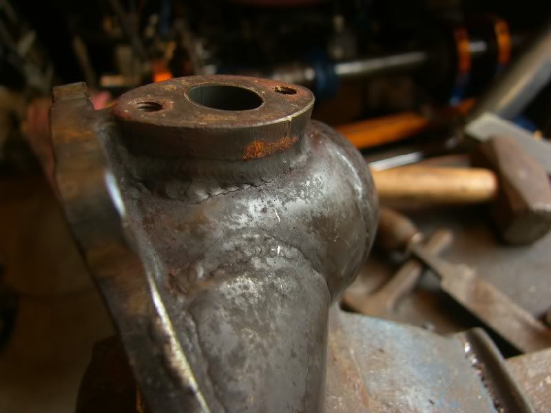
You can see it just below the O2 mount, there is actually a small one just above the lower weld too.
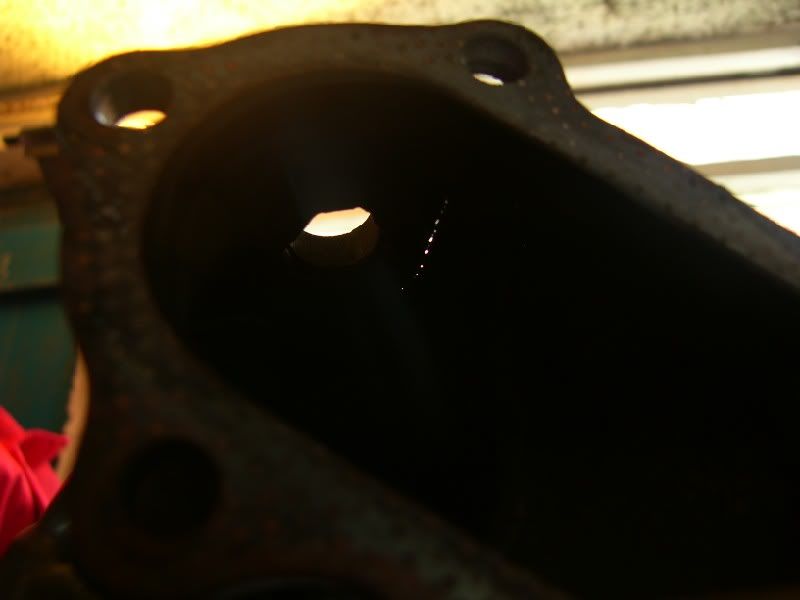
You can clearly see the crack from the inside –
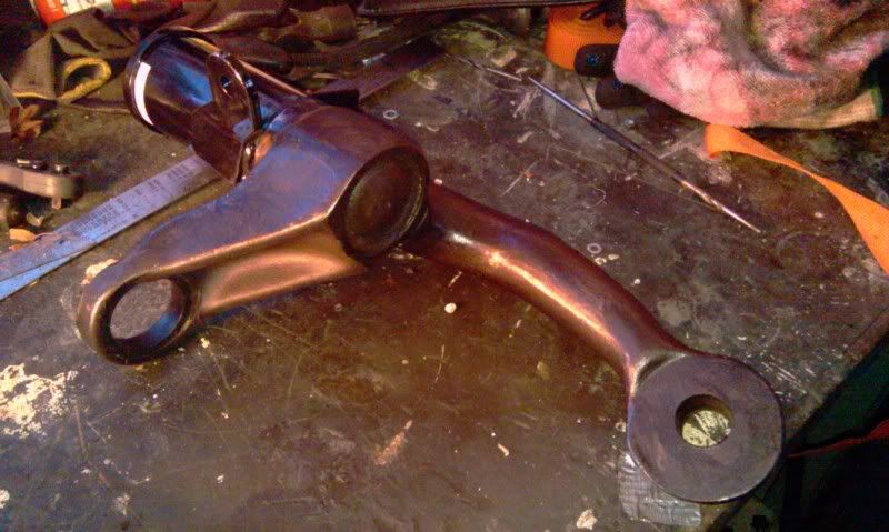
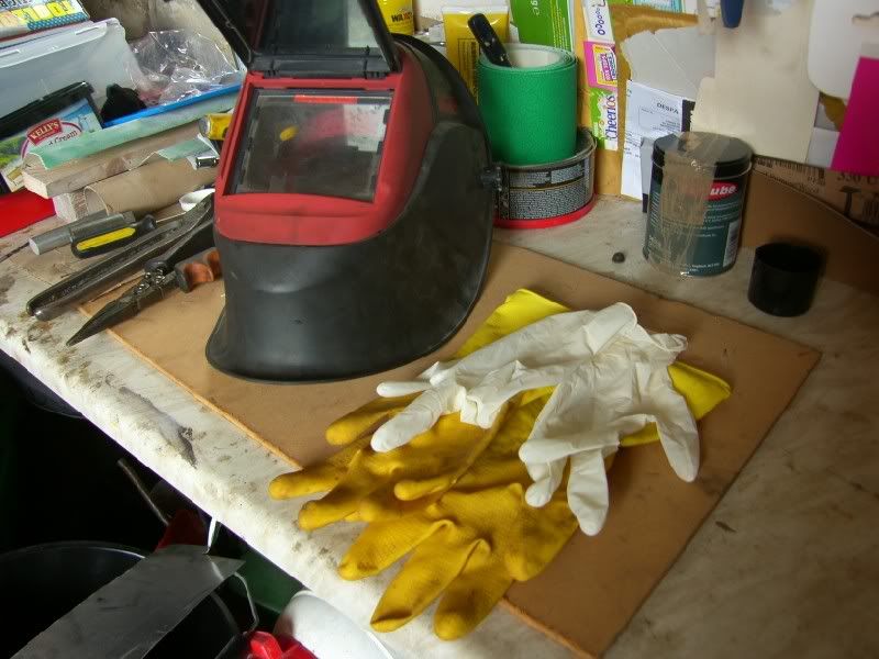
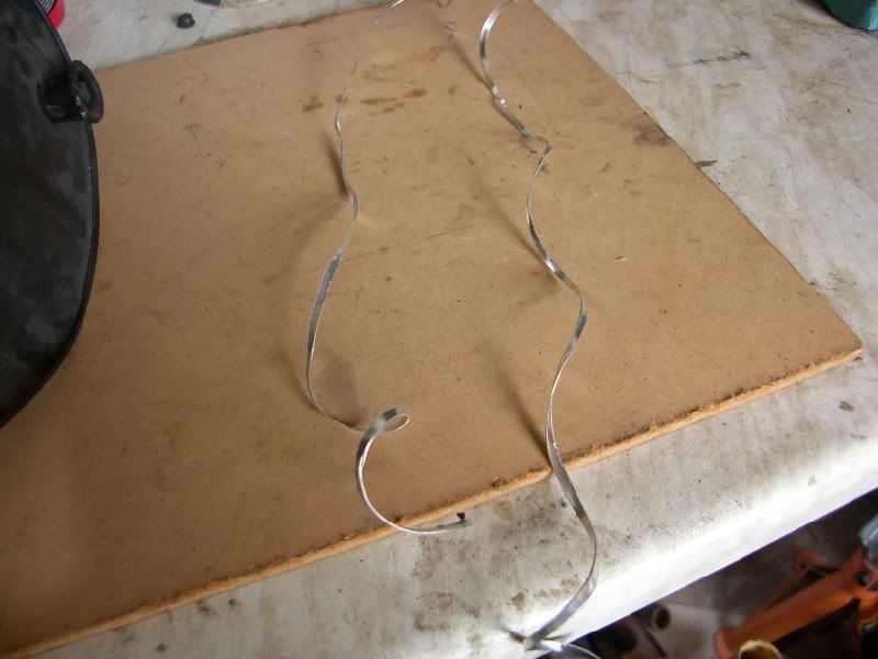
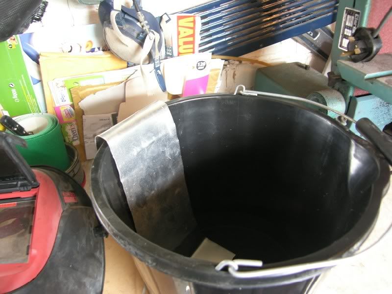
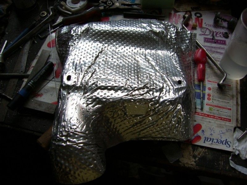
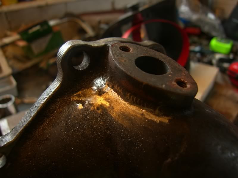
I cleaned it up with the dremel, sealed it off each end using tin foil and back purged it ready to TIG weld –
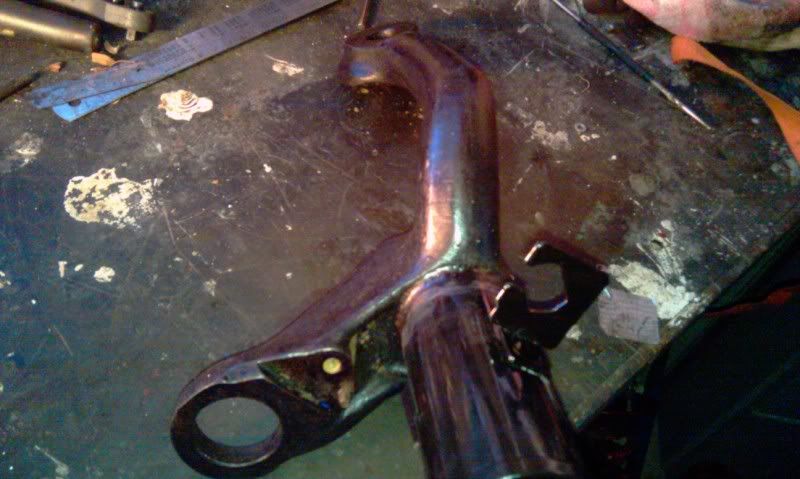
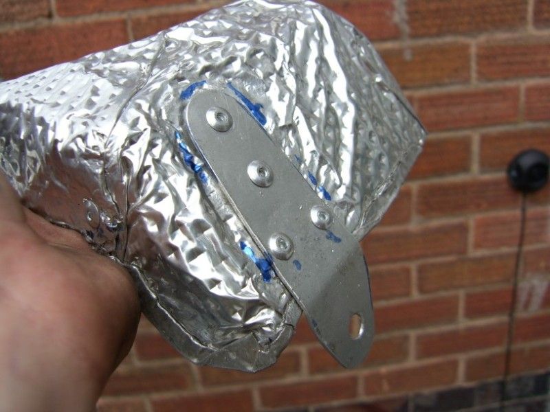
The finished article –
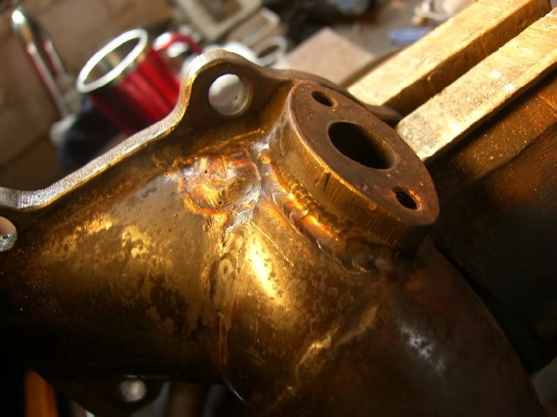
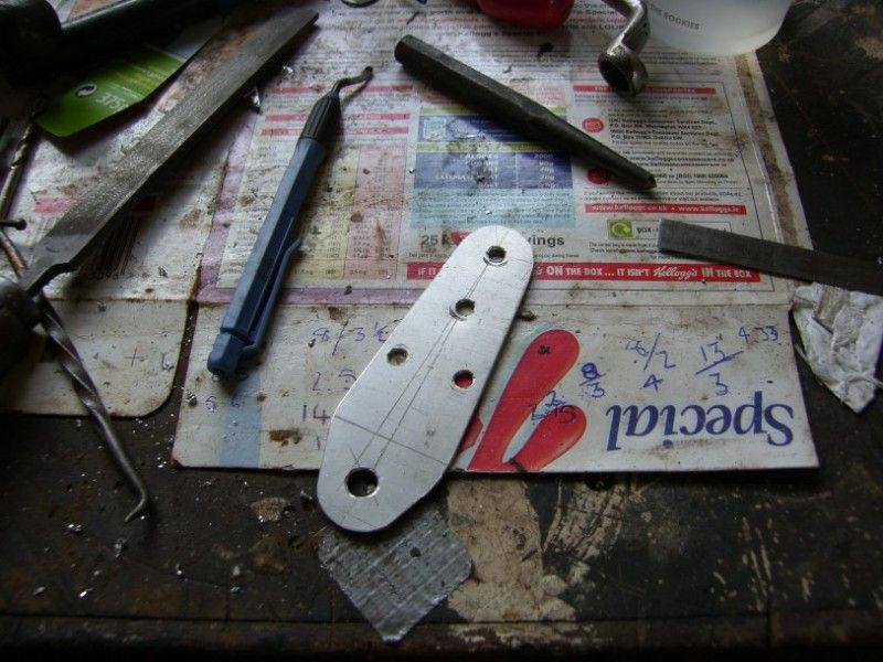
I had to weld a small patch on next to the line that covers the crack, the stainless was very very thin in that area an liable to crack again.
I have fitted it back on the car now and it is working fine, just sealed with exhaust paste atm until the gaskets arrive

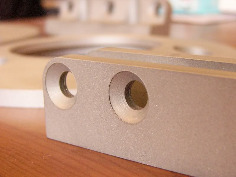
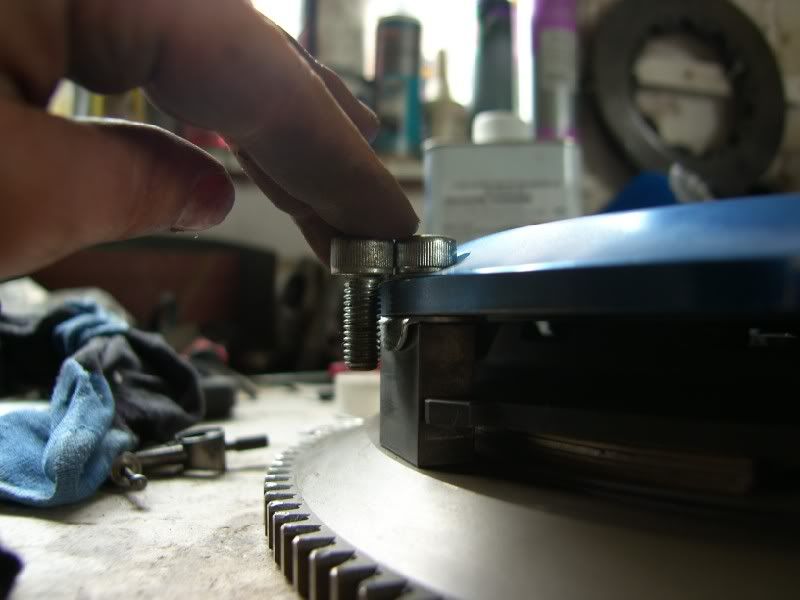
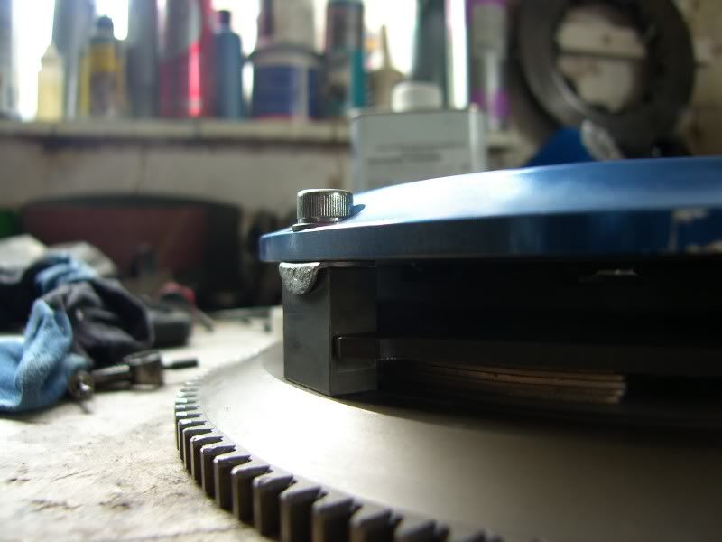
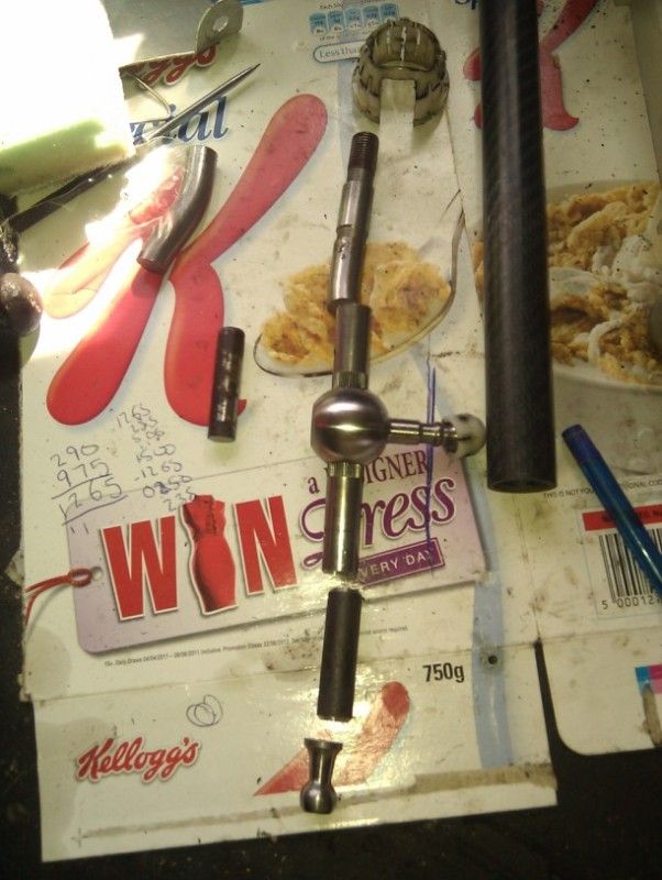
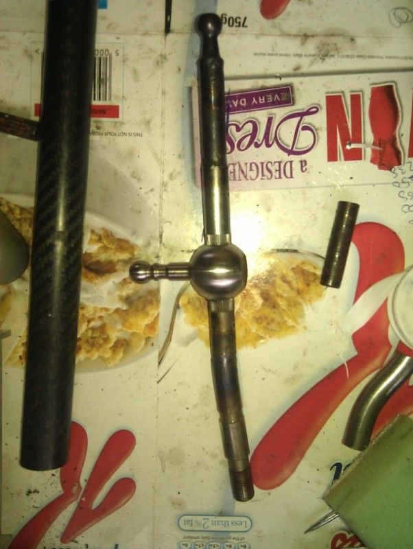
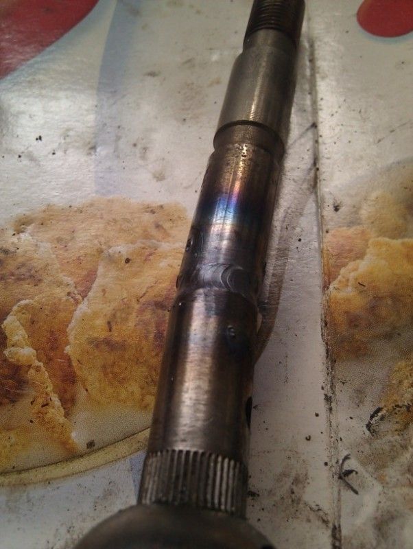
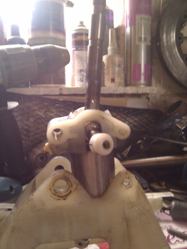
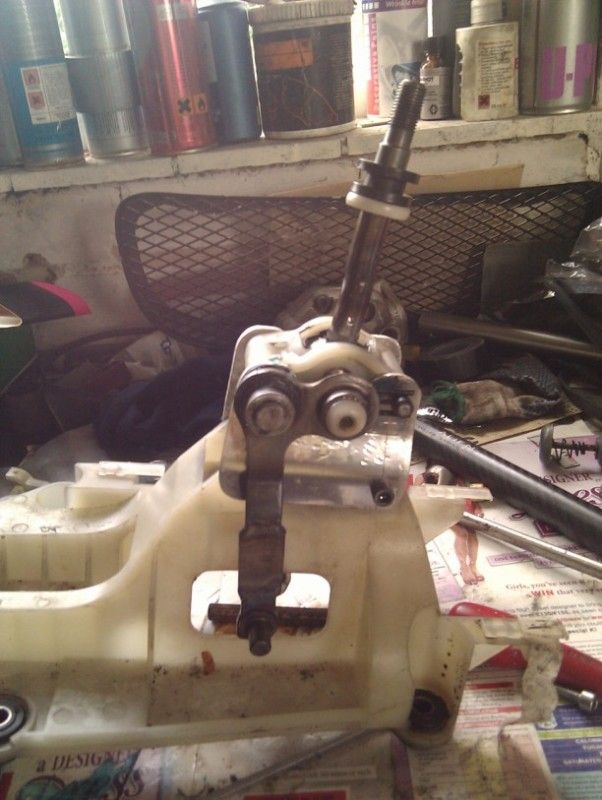
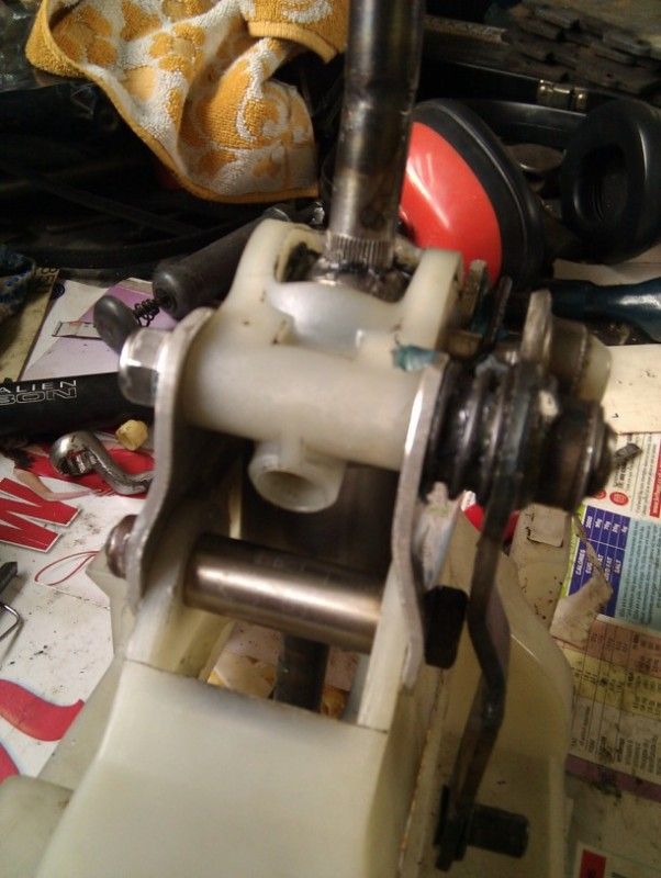
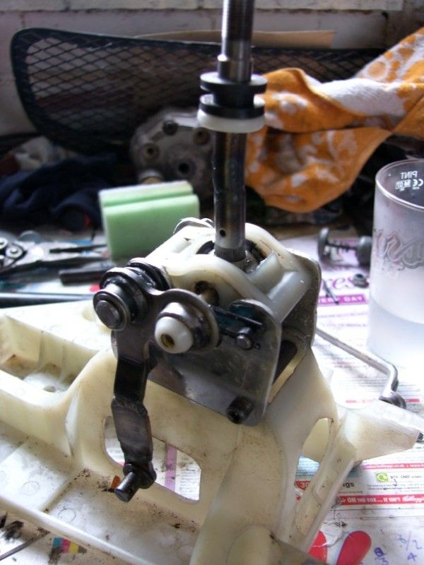
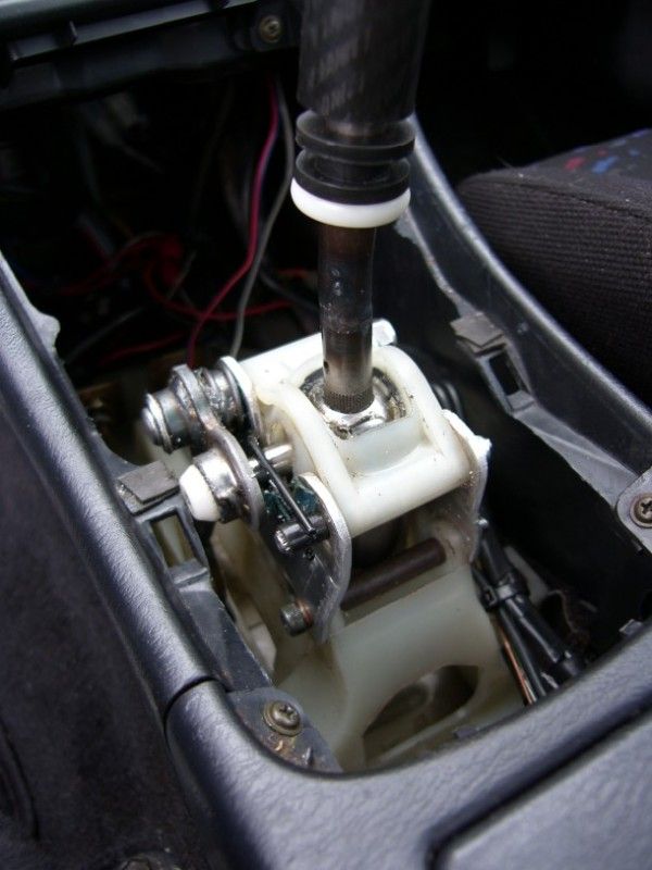
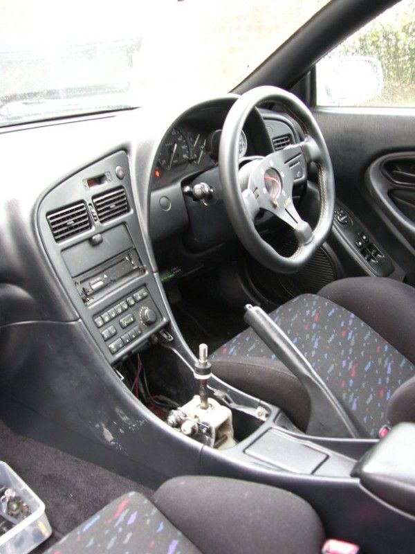
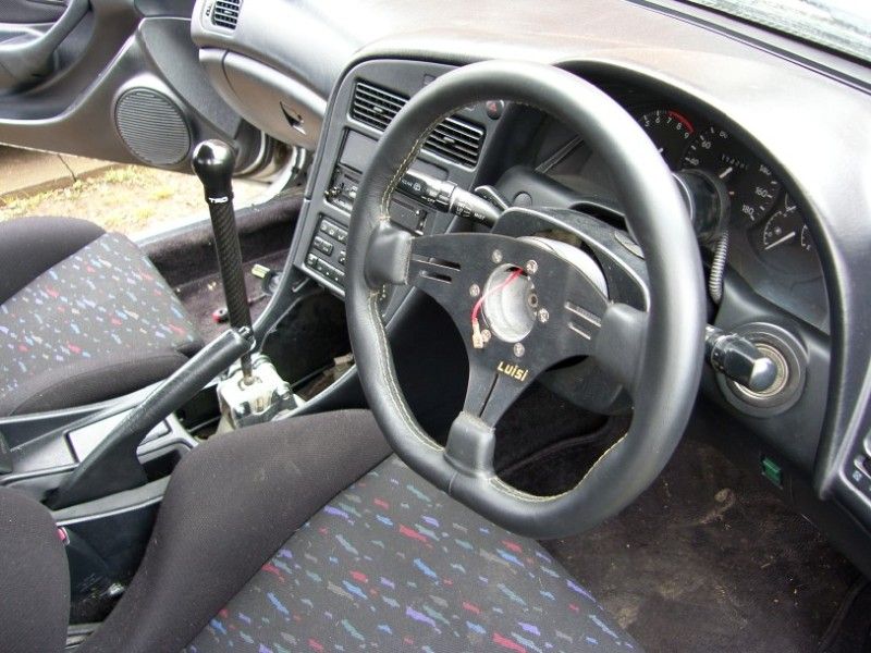
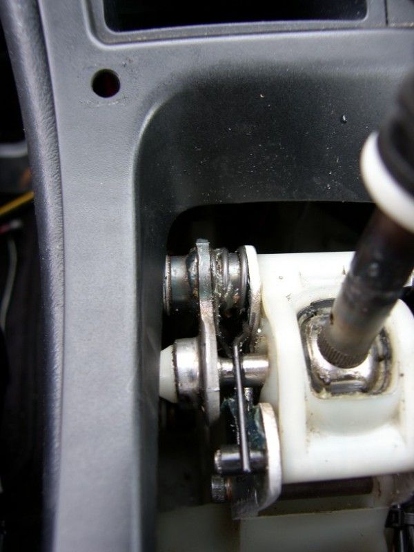
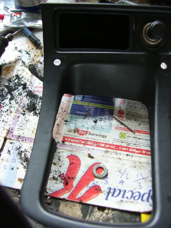
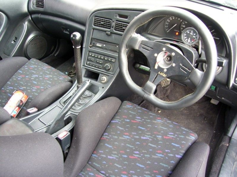
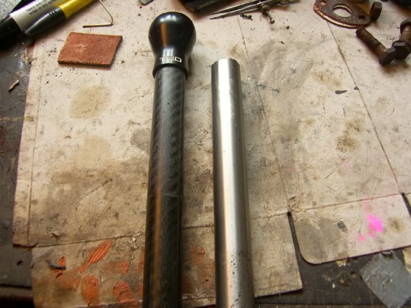
I have been fiddling with the gear shift and mount in the car too, I like to have the gear knob right next to the steering wheel if possible, the celica will be no different. The base mount will be spacered up by 30mm to allow the lower portion of the lever to be extended, then the top will be extended to keep the standard ratio but significantly lengthen the lever.
I was unsure what to lengthen the lever with, then upon inspection I found that the TRD shift knob has a straight bored hole in the bottom…..I wonder…..
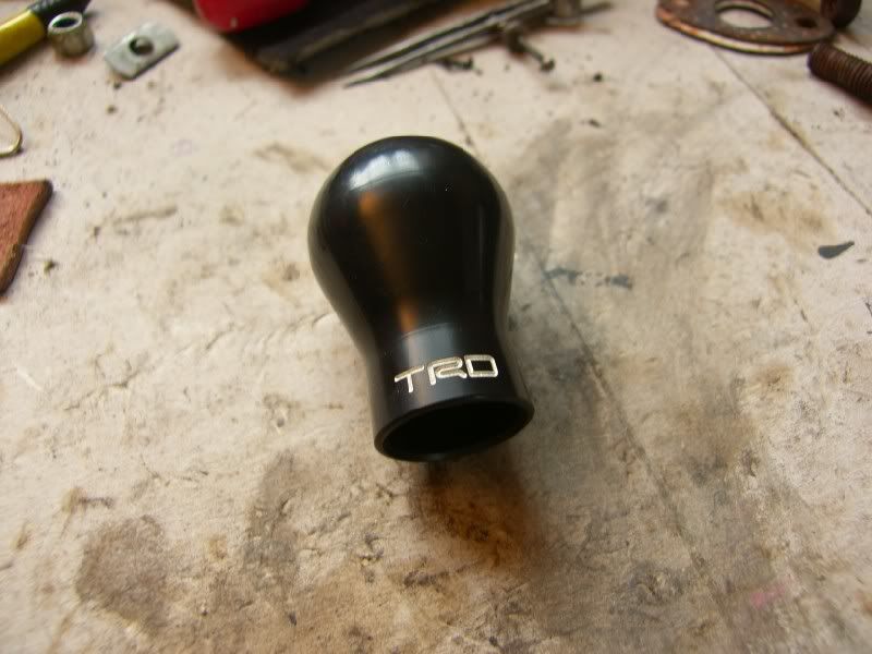
Hmmmmm, carbon or titanium????
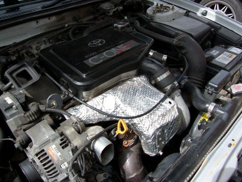
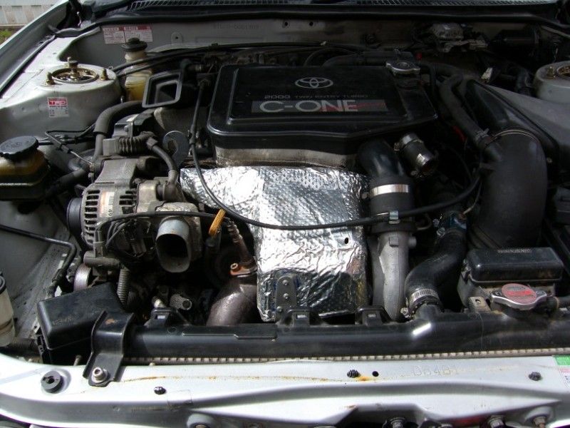
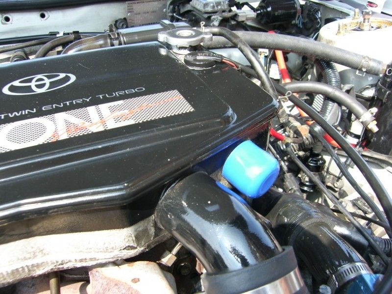
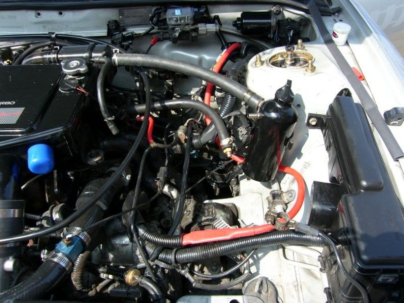
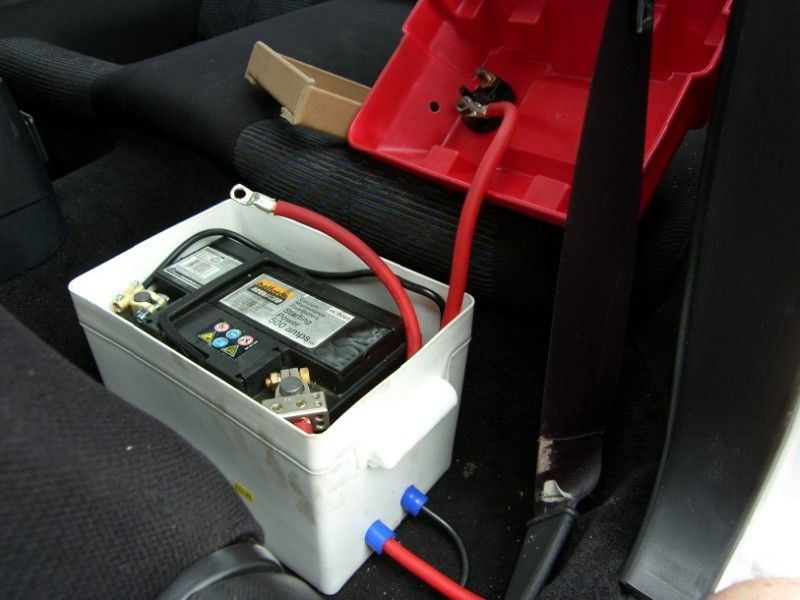
Apart from that, I have tidied up a lot of the wiring under the bonnet, removing the horn wiring and relays that were added at some point, only after investigating and finding that they were running a relay and fuse to run another relay and fuse!
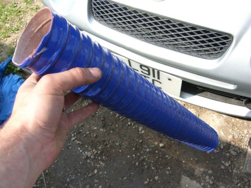
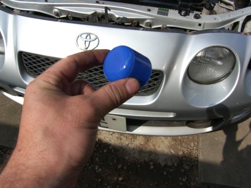
I have also tidied up a lot of the vacuum hosing and simplified the routing
Ok enough for now, I think I am going to enjoy driving it for a while
J