The TOMEI way. Stumbled upon this during one of my online JDM adventures. I've re-hosted all the pics for future reference.
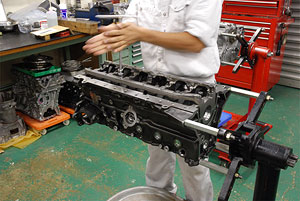
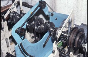
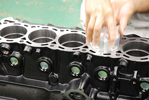
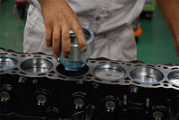
 Short block assembly

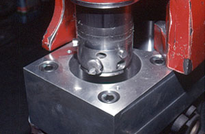
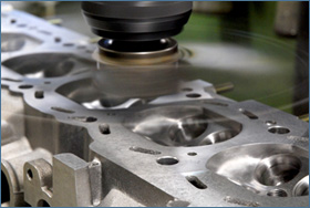
When the blocks surface is deformed which at times happens even with new blocks from factory it will need to be corrected. The surface is then milled and corrected within 0.1 mm accuracy. With the horizontal face corrected with a perfectly flat surface the meting face is improved which also improves sealing characteristics for maintaining the right combustion gas pressure.
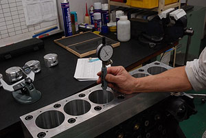
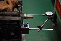
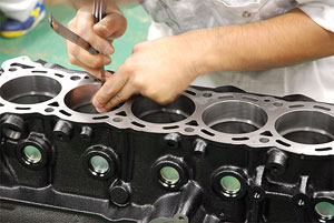
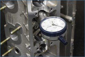
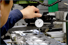
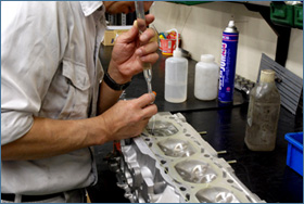
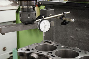 The horizontal surface face of the block is measured precisely with a dial gauge for the optimum results.
 With the milling machine making a perfectly flat surface cut with the strictest tolerances possible we are extremely meticulous with the measurements, room temperature settings, setup process and even the speed and timeframe of how each and every block is processed.

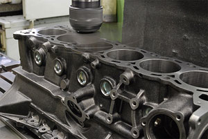
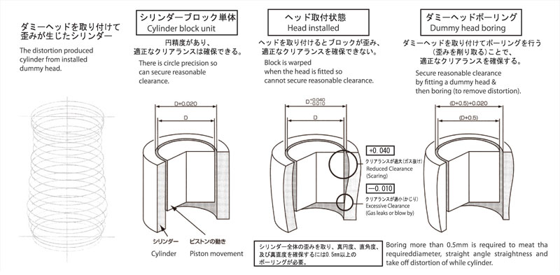
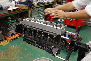
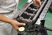
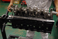
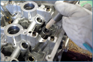
Boring the block with the dummy head attached greatly enhances the machining results so that during the boring process the block is not deformed more than 0.01 mm. This is another key factor in achieving the highest precision possible with each engine build. The block is assembled with a dummy head (of the same height as the stock head), head gasket and crank caps to replicate the same condition as an assembled engine.
 The crank caps are installed with the required torque settings.
 The head gasket is fitted with the right torque settings.

Boring with the dummy head helps improve the precision of each of the cylinder dimensions which minuses’ distortion. The results of boring the block with the dummy head attached are the best results for precision.
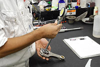
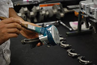
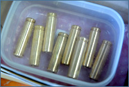
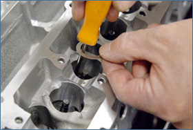
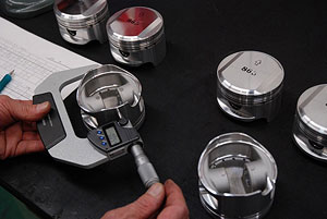 Each piston size is measured for finding the right size in which the cylinder should be bored at for the best piston to cylinder wall clearance.
 All machining is also processed in a climate controlled room where the temperature is maintained at a set ideal temperature to minimize the metal expansion for precision cutting.

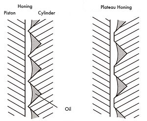
The small grooves made by the general honing is processed called the “cross hatch” style on the cylinder walls helps with holding oil on the cylinder wall surface for the best lubrication results for the pistons. The general rough surface finish of the cylinder walls will usually cause unwanted frictions. The plateau honing with the cross hatch layout will help smooth the surface more whilst still holding oil in the walls and greatly reducing fiction which greatly enhances the engines life and durability.
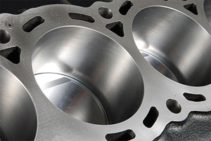 The plateau honing cross hatch can be seen on the cylinder walls surface.

The block is then left in the climate controlled room for a minimum of 24 hours to maintain a stable temperature at 20 ℃, this is the best temperature for checking and verifying piston clearance with tolerances kept within an acceptable range of ±5 μ.

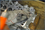
To maintain precision and the cylinder block is checked for any signs of imperfection from any unwanted burr and or debris that was caused during casting at the OEM manufacturer. This assures no unwanted matter will cause any harm during assembly and more importantly keeping the oil and waterlines completely clean to eliminate any troubles.
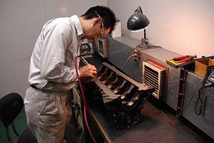

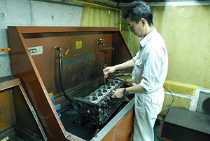
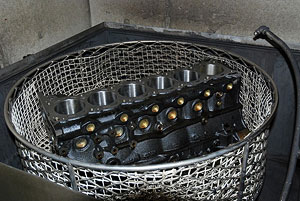
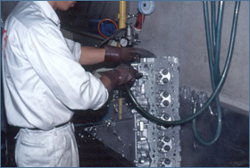
Complete cleaning of the water & oil lines is meticulously done by hand manually with each and every block with every orifice and areas checked thoroughly and then finished off with a high pressure and hot wash in a specialized machine and finally completed with a high pressure air clean in every line, gaps and orifices. This extensive 3 stage process is time consuming but an absolute must to completely eradicate any unwanted burr and foreign material from causing harm to the internals.

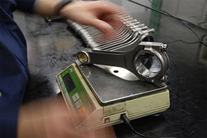
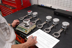
The Tomei products have already been checked and balanced when we packed them in the beginning. But we then re-check the weights again in various assembly stages when we assemble the short block. After the conrod and piston is assembled together we then again re-check the combined weights again to make sure that the weight difference is within 0.1 g from each other conrod and piston assembly. This will yield the best response, added power, smoother operations and extending engine life and durability.

The dynamic balancing of the crankshaft helps improve response, extra power gains, significally reduces unwanted vibrations which eases the stress on bearings to minimize rebuilds. The crankshaft is also checked for any signs of bends in the crank and for any other faults and if found it will be corrected during this process. Just another time intensive process that you will no longer have to worry about.

Each bearing clearance is carefully checked for guaranteeing that the right amount of oil film is maintained in the right areas for optimum lubrication of the crankshaft without causing any unwanted friction. The thrust direction is also checked and this entire process is also performed in a climate controlled room with all parts and essential equipment maintained at a constant 20 ℃.

The piston ring is designed to provide the best sealing properties and clearance. These piston rings are designed as a perfect circle for the protection of the cylinder walls and for maximum sealing properties. This also aids with the best protection possible for the cylinder walls for extending the life of the engine.

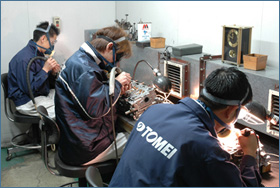
The final and most vital process is the complete assembly process is performed in the strictest standards with a clean environment in a stable climate controlled room in-house. All attention to details ensures "Precision & Perfection" that is the Tomei Powered standards and custom.
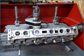
 Head assembly

1 VALVE GUIDE REPLACEMENTS
We heat the cylinder head up to 200 degrees C. to extract the stock valve guides. The difference in thermal expansion will allow an easy and safe removal process of the valve guides without damaging the head. Then we again heat the head prior to installation of the new Tomei valve guides. The Tomei valve guides are frozen to -200 degrees C with liquid nitrogen. So the total temperature difference of 400 degrees C will ensure the absolute best installation process, without the risk of damaging either the head or the new valve guides. This is how we also achieve the best seal and seating of our valve guides.
2 LARGER DIAMETER VALVE SHEET RINGS
When upgrading to oversized valves, larger valve seat rings are required. Just simply enlarging the seats to accommodate the larger diameter of the valve is not enough. Long term durability and optimized flow is all taken into account. New seats are cut, and both the intake and exhaust ports are corrected for improved head flow.
3 VALVE SEAT CUT
Each valve seat width, position and taper angles. The surface condition is checked and addressed to maximize the aerodynamics from the intake to the combustion chamber, and then out through the exhaust. Each seat is cut to suit each valves position and tapered angle. The surface angles and positions are all arranged to optimize overall flow. By increasing the sealing properties of the valve to valve seat, then more accurate compression can be maintained. This process is extremely time consuming, to find the optimum design for the engine and its application.
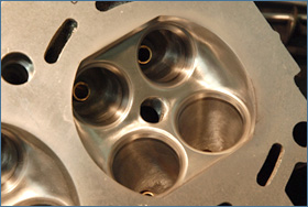
4 OPTIMIZING THE COMBUSTION CHAMBER
The valve seat rings surrounding area may have some imperfections from the factory. This can affects the combustion chambers volume and performance. So by targeting this area the flow can be optimized to maximize the already limited area. Deburring casting imperfections from the port to the seat rings and smoothing this area is an absolute must. Extra care and attention is taken into account for the airflow and dynamics of this area.
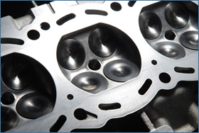
5 PORT STEP CORRECTIONS
Correcting the valve seat rings helps optimize the combustion chamber shape and makes the flow characteristics much better on the intake and exhaust side.
6 VALVE SPRING SETTING & ADJUSTMENTS
The valve springs will need to be upgraded to help keep a good balance for both low and high engine speeds. The added weight reduction will greatly help the valve train assembly. The key points are to set the correct load properties of each of the valve spring and also with the weight reduction factored in. The valve length extension is then checked to measure the correct valve seat cut required. Then the correct valve length is set with the use of the valve spring sheet adjustments. This process will increase the valve springs design efficiency which also means that the load is then set.
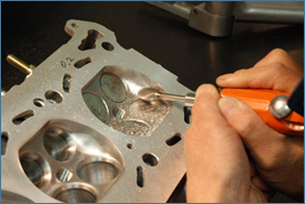
7 VALVE LAPPING
A special lapping compound is used to lap the valves and the seat rings to correct the sealing and contact areas of the valve with the seat ring. The correct adjustments can then be made to optimize sealing, to prevent any gas leaks. If the area is too large then there is a risk of grime or carbon buildup, this can then damage both the valves and seats, which will hinder performance. If it's too narrow, the high stress loads on the seats will reduce cooling efficiency as the heat cannot dissipate into the cylinder head effectively.
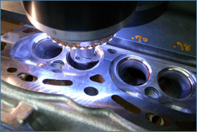
8 HEAD SURFACE CORRECTION
The head is checked for any signs of deformation, and then corrected with the mill cutter to make the appropriate corrections. This will increase the heads plane to improve sealing characteristics, with a secure flat face to met well to the cylinder block. Having corrected the face of the head will help increase compression and deliver more power.
9 CLEANING THE HEAD
The entire head is meticulously cleaned. Both the water and oil galleries and every orifice is cleaned by hand with various tools. Then it is finished off with a high pressure hot washing machine and then high pressurized air cleaning. Passing these 3 heavy processes, the head will come out looking brand new. An extensive check of the head will be done next, and the casting errors will be removed by hand.
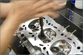
10 COMBUSTION CHAMBER CAPACITY ADJUSTMENTS
Large valve seat rings are fitted and adjusted. The valve seats are then cut and finally the combustion chambers are carefully calculated and adjusted to suit the target displacement on each cylinder. All Genesis engines have their cylinder compression chamber ratios all adjusted to suit the target volume. Meticulous attention to detail and precious adjustments of 0.1-0.9cc is normal in our standards to attain the optimum results.
11 PRECISION ASSEMBLY
Our staff is always striving for perfection. So "precision assembly" is always first priority on our work methods. This is why we have been around since the late 60's and still going strong. Our materials, equipment, work environment and management are specifically design to show in our end products results. Only with our strict standards is how we can achieve the high levels of standards that Tomei Powered is well known for.
Source:
http://www.tomei-p.co.jp