www.gt4dc.co.uk
Maintain, Modify and DRIVE your GT-Four


It is currently Fri Apr 19, 2024 6:35 pm


Post new topic Reply to topic  [ 61 posts ]  Go to page Previous  1, 2, 3, 4, 5  Next
Author Message
PostPosted: Fri Aug 02, 2013 10:24 pm 
Offline
WRC
User avatar

Joined: Tue Dec 09, 2008 6:51 pm
Posts: 1397
Location: Austria
Car Model: None
Hi,

i think that i can follow you, we did it like you said, each cop is switching 12V down over a resistor, but i think here is the problem, changing the resistor against a coil
could work to get a higher voltage or i have a look to the combi meter electronic for a better seight of things

but to bussy to got that problem solved that weekend :x

greetz

_________________
KEEP COOL UNDER PRESSURE
Image
street legal?.....perhaps in tschibuti


Top
 Profile  
 
PostPosted: Mon Aug 12, 2013 10:57 am 
Offline
WRC
User avatar

Joined: Tue Dec 09, 2008 6:51 pm
Posts: 1397
Location: Austria
Car Model: None
Hi,

not solved yet, but the next electronic is ready to try in the next few days, not we use PNP transistor and use the coils to trigger him.....if it works i post can post a draw for a do it yourself job if in need

nibbles, now i understand you, you means to use the ecu output line for the rpm meter?

greetz

_________________
KEEP COOL UNDER PRESSURE
Image
street legal?.....perhaps in tschibuti


Last edited by Sunny on Mon Aug 12, 2013 10:58 am, edited 1 time in total.

Top
 Profile  
 
PostPosted: Mon Aug 12, 2013 10:58 am 
Offline
WRC
User avatar

Joined: Tue Dec 09, 2008 6:51 pm
Posts: 1397
Location: Austria
Car Model: None
-----sry

_________________
KEEP COOL UNDER PRESSURE
Image
street legal?.....perhaps in tschibuti


Top
 Profile  
 
PostPosted: Mon Aug 12, 2013 12:38 pm 
Offline
Group N
User avatar

Joined: Sat Apr 01, 2006 7:43 pm
Posts: 398
Location: Parma - Italy
Car Model: None
Sunny wrote:
Hi,

not solved yet, but the next electronic is ready to try in the next few days, not we use PNP transistor and use the coils to trigger him.....if it works i post can post a draw for a do it yourself job if in need

nibbles, now i understand you, you means to use the ecu output line for the rpm meter?

greetz


Wolf_Tm wrote:
Sunny,
please reply to the question I made you some days ago, so I can understand WHY you want/need to touch the injectors wirings.

Wolf_Tm wrote:
Sunny wrote:
Hi,

any tips how i can make the cops working together with the rpm meter of the cluster?


Do you have any available output on your Haltech ecu?


Dear Sunny,
It's almost ONE MONTH I'm asking you if you have an available ecu output.
Why do you have to contact me privately on this issue, if then you don't reply to my message here?

Guys, do you see my messages in this thread or am I the only one?

:?:

_________________
Wolf_Tm
TM 250 enduro 2 stroke
GT-four ST205 Snowy White with selfmade 3SGTE v4.1 - [2.34kg/bhp DynoDynamics]
http://www.youtube.com/WolfTm250
http://www.facebook.com/wolf.tm


Top
 Profile  
 
PostPosted: Mon Aug 12, 2013 1:27 pm 
Offline
Group B
User avatar

Joined: Sat Sep 02, 2006 3:13 pm
Posts: 3679
Location: Bournemouth
Car Model: None
Sunny wrote:
Hi,

not solved yet, but the next electronic is ready to try in the next few days, not we use PNP transistor and use the coils to trigger him.....if it works i post can post a draw for a do it yourself job if in need

nibbles, now i understand you, you means to use the ecu output line for the rpm meter?

greetz


Wolf_Tm wrote:
Sunny,
please reply to the question I made you some days ago, so I can understand WHY you want/need to touch the injectors wirings.

Wolf_Tm wrote:
Sunny wrote:
Hi,

any tips how i can make the cops working together with the rpm meter of the cluster?


Do you have any available output on your Haltech ecu?


Dear Sunny,
It's almost ONE MONTH I'm asking you if you have an available ecu output.
Why do you have to contact me privately on this issue, if then you don't reply to my message here?

Guys, do you see my messages in this thread or am I the only one?

:?:


There was another thread a while ago on the issue, and it seems there isn't an available output for this function.

_________________
If at first you don't suck seed, try drier grain.

Image


Top
 Profile  
 
PostPosted: Mon Aug 12, 2013 1:30 pm 
Offline
Group B
User avatar

Joined: Sat Sep 02, 2006 3:13 pm
Posts: 3679
Location: Bournemouth
Car Model: None
Sunny wrote:
Hi,

not solved yet, but the next electronic is ready to try in the next few days, not we use PNP transistor and use the coils to trigger him.....if it works i post can post a draw for a do it yourself job if in need

nibbles, now i understand you, you means to use the ecu output line for the rpm meter?

greetz


Sorry, I missed this post.

Yes indeed, I was planning on using the drive signal from ECU to injector.

If you are saying the injectors have an extra 'tacho' output which pulls to ground, then you should be able to use these with a diode on each (bar towards injector) and a pull-up resistor (1K or 4K7) to 12V on the tacho. No transistor needed.

_________________
If at first you don't suck seed, try drier grain.

Image


Top
 Profile  
 
PostPosted: Mon Aug 12, 2013 8:38 pm 
Offline
Group N
User avatar

Joined: Sat Apr 01, 2006 7:43 pm
Posts: 398
Location: Parma - Italy
Car Model: None
Nibbles wrote:

There was another thread a while ago on the issue, and it seems there isn't an available output for this function.


Oh, at last... not the OP but... thanks.

_________________
Wolf_Tm
TM 250 enduro 2 stroke
GT-four ST205 Snowy White with selfmade 3SGTE v4.1 - [2.34kg/bhp DynoDynamics]
http://www.youtube.com/WolfTm250
http://www.facebook.com/wolf.tm


Top
 Profile  
 
PostPosted: Mon Aug 12, 2013 9:48 pm 
Offline
WRC
User avatar

Joined: Tue Dec 09, 2008 6:51 pm
Posts: 1397
Location: Austria
Car Model: None
Hi,

sorry, looks like i missed that PM :)

yes i can programm a output from the ecu, with a coil or by eliminating the resistor in the rpm-meter it should work

thats plan B now, currently i must work with the cops to drive the meter, i don't allow me that i can't can made it working that way :lol:

greetz

_________________
KEEP COOL UNDER PRESSURE
Image
street legal?.....perhaps in tschibuti


Top
 Profile  
 
PostPosted: Wed Sep 11, 2013 7:15 pm 
Offline
WRC
User avatar

Joined: Tue Dec 09, 2008 6:51 pm
Posts: 1397
Location: Austria
Car Model: None
Hi,

just an updated, i just changed the 43kOhm resistor in the rpm gauge against a 120Ohm and now i use the 5V tacho channel on the haltech to controll the meter, pretty simple


greetz

_________________
KEEP COOL UNDER PRESSURE
Image
street legal?.....perhaps in tschibuti


Top
 Profile  
 
PostPosted: Wed Oct 23, 2013 12:53 am 
Offline
Club Staff
User avatar

Joined: Wed Jul 13, 2005 12:06 am
Posts: 4743
Location: Perth, Western Australia
Car Model: ST205
Finally solved the mystery of the Coil on Plug kit parts supplied by RacerX in the USA.

RacerX didn't supply any fitting instructions but how difficult could it be? :lol: :roll: I naively assumed that the kit parts replaced the dizzy with a cam trigger sensor. When I couldn't work it out I emailed Jeff at RacerX and he sent me a link to his thread on the MR2OC forum. You need to be registered to view but sadly this is nowhere near as easy as our DC forum :cry: ....however with some help from JP I have found a wealth of info on the site. It appears that the original COP kit cam trigger has been replaced with a blanking plug to replace the entire distributor assembly. The fact they'd included an alloy dizzy cap in the kit led me astray. There is no need for this if you use the blanking plug.

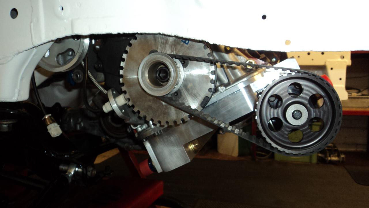
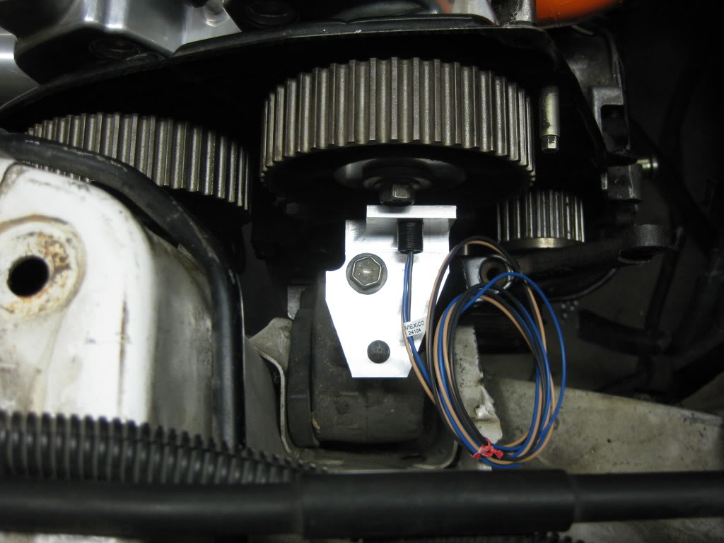
The cam trigger Cherry Hall sensor in the updated kit is now mounted on the alloy bracket bolted to the drivers side engine mount and the slotted disc is mounted on the exhaust cam timing wheel. The only problem is the engine mount on the ST205 is completely different to the MR2 so you can't use the alloy bracket as supplied. The solution we have come up with is to fabricate a new bracket which will bolt on to the alternator bracket. This is rigidly bolted to the engine so won't flex or vibrate under load. The photos below should illustrate the situation.

Kit photos courtesy of RacerX (www.racerxfabrication.com), others are mine


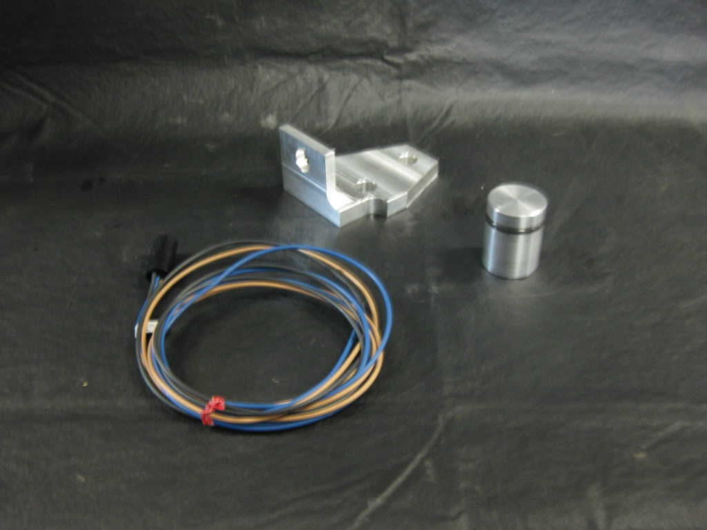
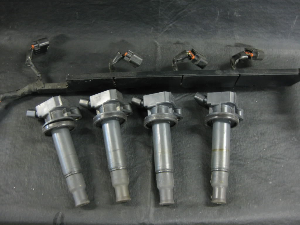
Cam trigger sensor, mounting plate and distributor plug

Image


1ZZ-FE Coil in Plug

Image


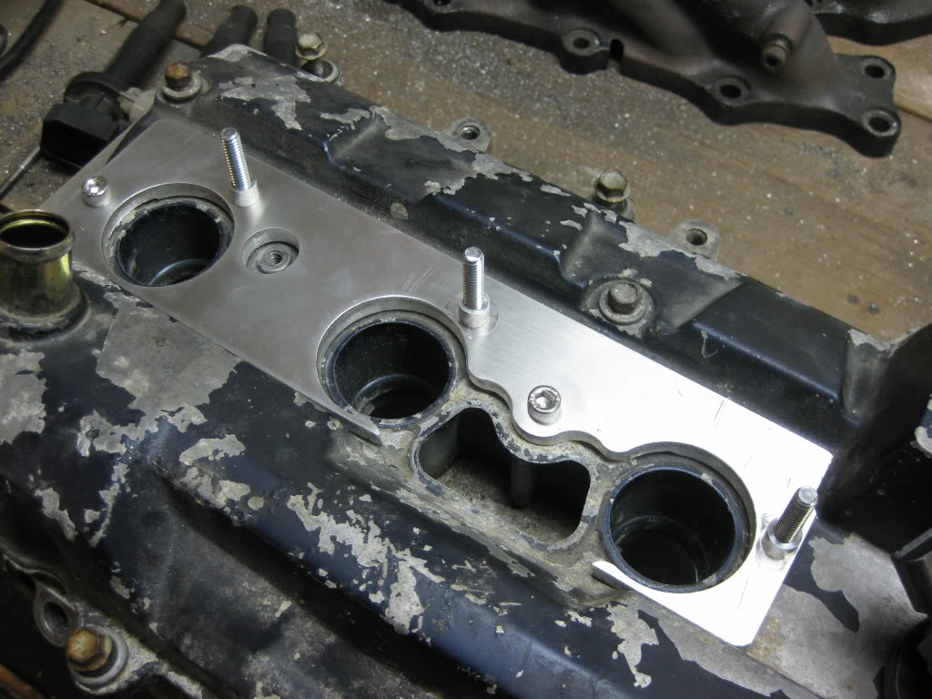
Coil on Plug Mounting Plate. This could be modified so that the orientation of the COP's is aligned. The RacerX kit assumes it has to make allowances for MR2 clearances but on my build we don't have these issues

Image


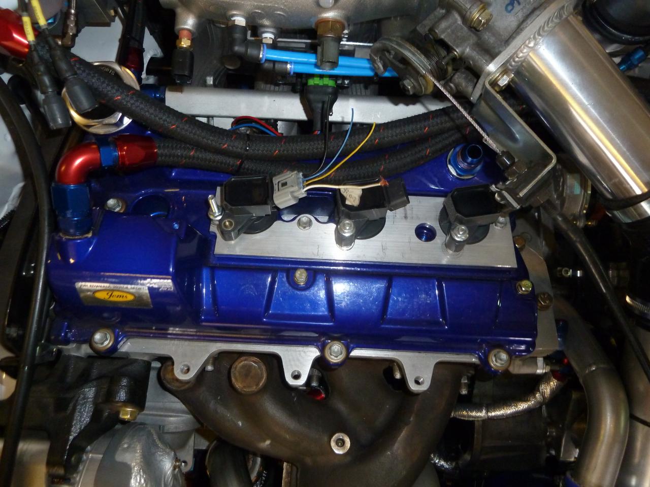
As installed on Track Toy. The plugs and tails were also supplied in the kit. Plan is to fit a flexible rubber boot which will fit over the top of the standard Denso plugs and make it look more professional

Image


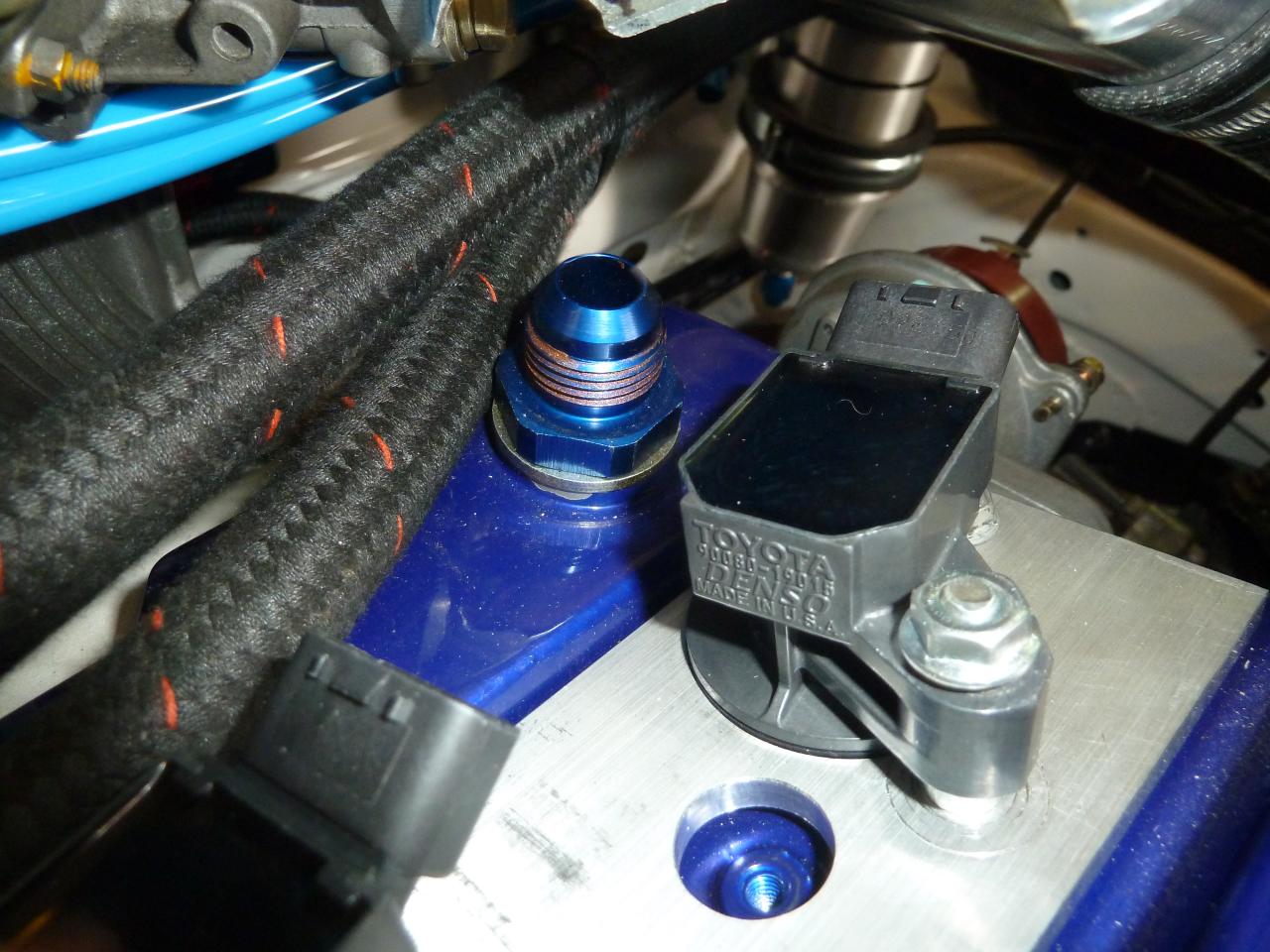
Toyota 90080-19015 1Z-FE Coil on Plugs by Denso - Made in the USA! Good for up to 700bhp output 3S-GTE according to the guys on the MR2OC forum

Image


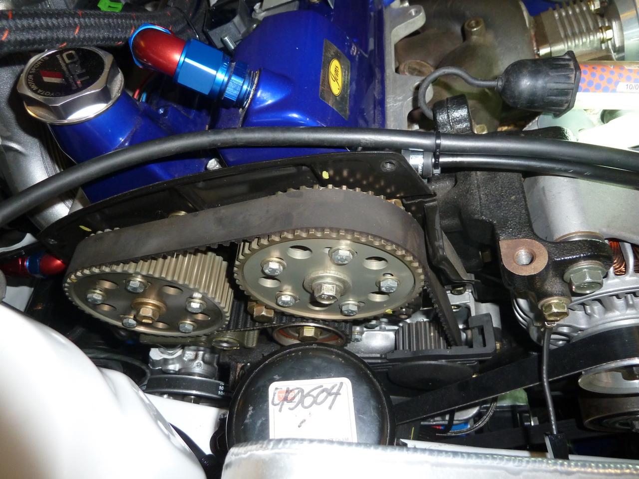
Track Toy cam timing cover removed. I'm not sure if it will be possible to re-fit the cam timing cover with the sensor installed. I guess a slot could be cut for the bracket/sensor but it would look like a bit of a bodge. I'm sure a neater solution is possible.

Image


RacerX MR2 cam sensor installation

Image


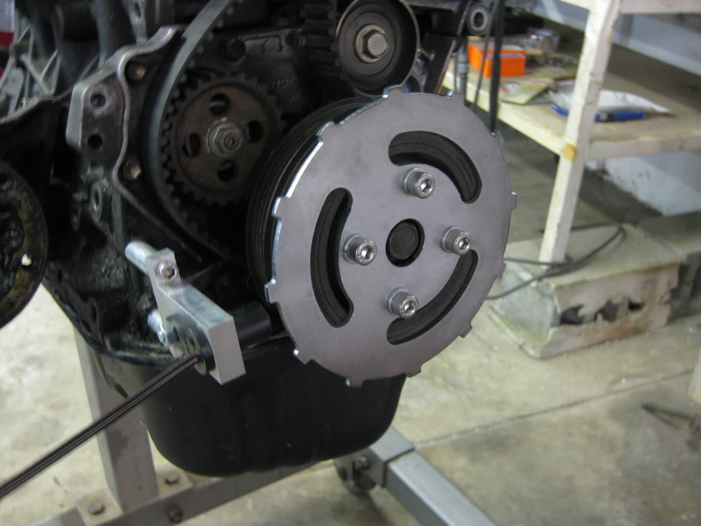
RacerX 12 tooth crank sensor installation. I didn't buy this as I had cloned a crank trigger borrowed from JP. RacerX also sell a 36-1 and a 60-2 wheel for finer adjustment at high rpm. Just thought I'd include for completeness

Image


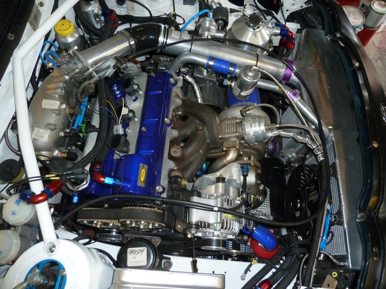
Track Toy engine bay

Image

_________________
Don
GT4DC Chairman
1994 Toyota Celica GT-Four ST205WRC JDM 269bhp @ 0.9bar
1994 Toyota Celica GT-Four Special GT 590bhp @ 1.8bar
1989 Van Diemen RF88/89 Formula Ford 1600
2008 Nissan Patrol GU 3.0L ZD30DDTi 154bhp


Top
 Profile  
 
PostPosted: Wed Oct 23, 2013 7:29 am 
Offline
Club Staff
User avatar

Joined: Wed Jul 13, 2005 12:14 am
Posts: 3265
Location: Camberley, Surrey
Car Model: ST205
Very interesting Don. :D

_________________
GT4DC Events Co-ordinator
1996 ST205 UK


Top
 Profile  
 
PostPosted: Fri Oct 25, 2013 7:27 pm 
Offline
WRC
User avatar

Joined: Tue Dec 09, 2008 6:51 pm
Posts: 1397
Location: Austria
Car Model: None
Hi,

i think the cam position sensor should follow the engines motions..... :?

greedz

_________________
KEEP COOL UNDER PRESSURE
Image
street legal?.....perhaps in tschibuti


Top
 Profile  
 
PostPosted: Fri Oct 25, 2013 10:02 pm 
Offline
Club Staff
User avatar

Joined: Wed Jul 13, 2005 12:06 am
Posts: 4743
Location: Perth, Western Australia
Car Model: ST205
Sunny wrote:
i think the cam position sensor should follow the engines motions..... :?
Yeah, I agree Sunny. The MR2 location on the engine mount isn't ideal as the sensor may move relative to the trigger disc on the cam wheel. The engine does move on its rubber mounts so I think its best to mount the sensor and its bracket on the engine. The alternator assembly looks like a good place to mount the sensor bracket.

_________________
Don
GT4DC Chairman
1994 Toyota Celica GT-Four ST205WRC JDM 269bhp @ 0.9bar
1994 Toyota Celica GT-Four Special GT 590bhp @ 1.8bar
1989 Van Diemen RF88/89 Formula Ford 1600
2008 Nissan Patrol GU 3.0L ZD30DDTi 154bhp


Top
 Profile  
 
PostPosted: Fri Oct 25, 2013 10:05 pm 
Offline
Club Staff
User avatar

Joined: Wed Jul 13, 2005 6:54 pm
Posts: 3484
Location: On Top
Car Model: None
Sunny wrote:
Hi,

i think the cam position sensor should follow the engines motions..... :?

greedz


Agree, how critical it is I don't know seeing as Don is using a crank sensor for ultimate rotation speed.
IMHO I would mod the dizzy cover to take a sensor and fab up a cam timing wheel to fit the slot in the end. It is more difficult but IMHO the correct way to do it. I do see that the bracket 7 sensor is fixed to the rigid end of the engine mount but how rigid is rigid enough?

Maybe I have missed the point of what you are doing but your crank sensor doesn't seem to have a missing tooth to indicate TDC of cyl 1. If you incorporate a missing tooth or single trigger on the cam then it will be fine.

I guess the ideal is to have a "many tooth" crank sensor for positional accuracy and a single cam trigger for cyl 1 TDC for ultimate position info. (you only the COP once every 2 revolutions so you only need a crank sensor to indicate when it is going to be on the "fire" stroke)

_________________
JP
GT4DC Treasurer

Grey St185 RC
Silver BMW E46 M3
Multicolour yawn Honda VFR400
Silver Honda Civic Type-R


Top
 Profile  
 
PostPosted: Sat Oct 26, 2013 12:09 am 
Offline
Club Staff
User avatar

Joined: Wed Jul 13, 2005 12:06 am
Posts: 4743
Location: Perth, Western Australia
Car Model: ST205
The kit includes an aluminium disc with a slot cut in the perimeter. It doesn't show well in the photo but you can just see the disc bolted to the exhaust cam pulley wheel. Without this cam sensor and just the crank trigger sensor the plugs would fire every revolution i.e. 'wasted spark'. The cam trigger means that the plugs only fire on the power stroke. This should be more efficient and ensure maximum energy to the COP and also avoid the COP's getting too hot by firing on very stroke.

I had a good examine of a spare dizzy and its not obvious how you to dismantle it. What is clear is the inner part of the dizzy wheel has a single tooth which performs the function of TDC sensor. The original RacerX kit replaced the entire dizzy including the allow housing with the cam sensor disc driven by a replacement spindle. There were more parts to manufacture and they ended up with the Mk2 version which you see above which is simpler and cheaper to make. Some instructions would have been useful but once I was able to access the RacerX thread on the MR2 board it all made sense.

The pic below shows the crank trigger wheel and sensor arrangement I am using . Note the missing tooth for TDC!

Image

If anybody is interested in pics of the original RacerX kit I can post them up?

_________________
Don
GT4DC Chairman
1994 Toyota Celica GT-Four ST205WRC JDM 269bhp @ 0.9bar
1994 Toyota Celica GT-Four Special GT 590bhp @ 1.8bar
1989 Van Diemen RF88/89 Formula Ford 1600
2008 Nissan Patrol GU 3.0L ZD30DDTi 154bhp


Top
 Profile  
 
Display posts from previous:  Sort by  
Post new topic Reply to topic  [ 61 posts ]  Go to page Previous  1, 2, 3, 4, 5  Next


Who is online

Users browsing this forum: No registered users and 17 guests


You cannot post new topics in this forum
You cannot reply to topics in this forum
You cannot edit your posts in this forum
You cannot delete your posts in this forum

Search for:
Jump to:  
cron
Powered by phpBB® Forum Software © phpBB Group