| Remove old mount from car (see how to coming soon) | |
| Using a marker of some description (I used Tippex) make some index marks from the rubber to the inner and outer metalwork. You will need these later to partially re-assemble the mount | |
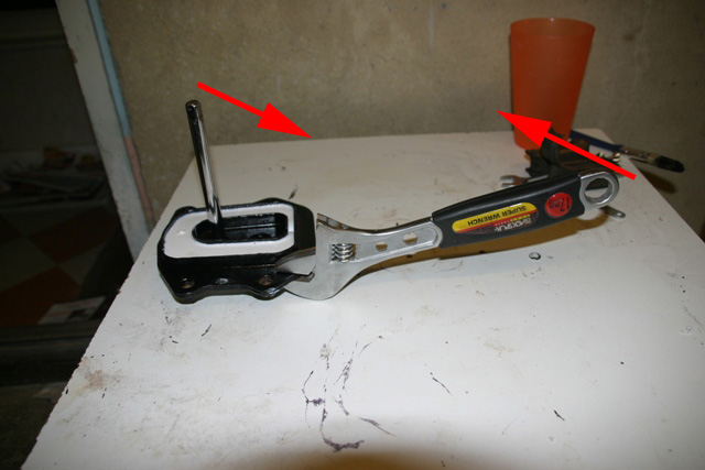 |
Using a prybar (I found a 3/8" socket extension bar to be about right) lever the central metal section from the outer frame. I did this by sticking the prybar through one of the two differential bolt holes and twisting the centre while holding the outer frame rigid with an adjustable. NB the photo here shows the completed mount as I forgot to take one of the original |
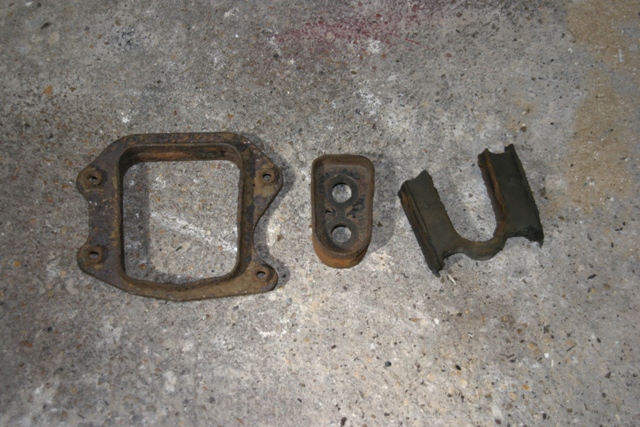 |
After grunting and groaning you should hopefully be left with 3 pieces, the rubber and inner and outer frames. Note that you need to take some care in the disassembly process. You need the rubber in one piece for the next stage |
| You will notice that on both edges the rubber has a tongue which engages in a groove in both the inner and outer frames. Using a craft knife CAREFULLY remove this tongue from both sides of the rubber. You should now find that you can re-assemble the mount relatively easily | |
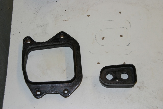 |
Re-assemble the mount and line up your match marks to get the original spacing back. When it's all lined up screw it down. Carefully remove the rubber and draw round the inner and outer frames so that you can re-position them later. You can see my outlines in the picture. You can now unscrew everything and prep and paint the metalwork. You can see here that I used a flat sheet of melamine board as the base. I think this could be improved on (detailed later) but as I know this works this is what I have detailed. Personally I wire brushed off the worst of the rust from the metalwork, hit it with a coat of KuRust then a coat of Hammerite. The result could be better though and is best described as a triumph of function over form |
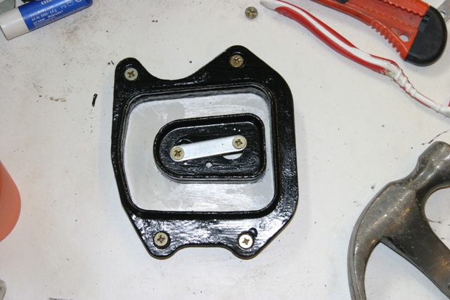 |
Coat the base with a suitable release agent. The product I used has a specific release agent or suggests the use of
Vaseline. Since I had neither I actually used a thin layer of teflon silicon grease. This worked fine for me but is not exactly following manufacturers instructions so may not work for other polyurethane resins Once you have applied release agent re-assemble the diff mount using the outlines you drew earlier. You can see my assembled setup here, with the shiny grease evident in the bottom Here is where I made a bit of a mistake. I used a little extra grease round the outline of both metal bits hoping that this would form a seal between the metal and the board when everything was screwed down. This proved not to be the case and I suffered some leakage in the next step. I think this is where my improved method would work but, again, as I have not tried it I have not described it. |
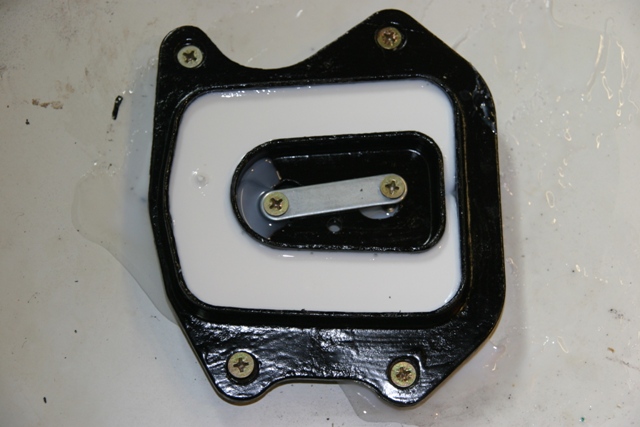 |
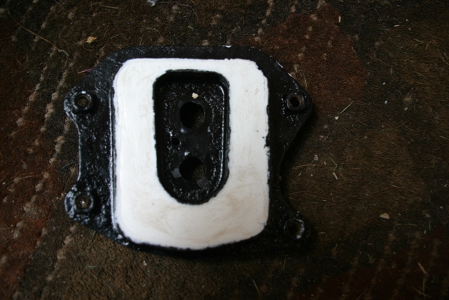
Mix the polyurethane resin following the manufacturer's instructions and carefully pour it into the void where the rubber was on the original mounting. I guessed the amount by eye but would estimate that 225 mL would be plenty. You should end up with something that looks like the picture, hopefully without the leakage that's evident in this picture. Leave the mount to cure following manufacturer's instructions |
|
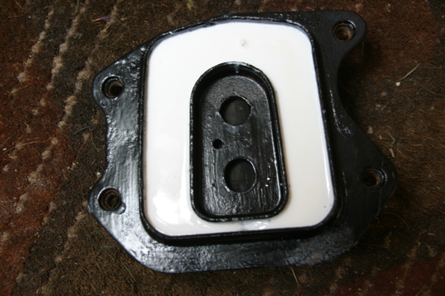
The finished article after a little trimming of the leaked resin |